
Microelectronics: Circuit Analysis and Design
4th Edition
ISBN: 9780073380643
Author: Donald A. Neamen
Publisher: McGraw-Hill Companies, The
expand_more
expand_more
format_list_bulleted
Concept explainers
Videos
Textbook Question
Chapter 15, Problem 15.60P
The saturated output voltages of the comparator in Figure P15.60 are± 10 V. (a) Find
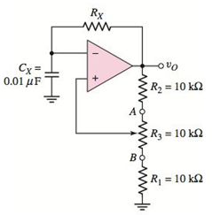
Figure P15.60
Expert Solution & Answer
Want to see the full answer?
Check out a sample textbook solution
Students have asked these similar questions
1a. Why is the input impedance to a JFET so high?
b. Why is the terminology field effect appropriate for this important three- terminal device?
What design specification will be improved with a PD compensator?
What is the minimum sampling rate needed in order to successfully capture frequencies up to 80MHz in an analog signal?
Chapter 15 Solutions
Microelectronics: Circuit Analysis and Design
Ch. 15 - Design a twopole lowpass Butterworth filter with a...Ch. 15 - Consider the switchedcapacitor circuit in Figure...Ch. 15 - Prob. 15.3EPCh. 15 - (a) Design a threepole highpass Butterworth active...Ch. 15 - Prob. 15.2TYUCh. 15 - Prob. 15.3TYUCh. 15 - Simulate a 25M resistance using the circuit in...Ch. 15 - Design the phaseshift oscillator shown in Figure...Ch. 15 - Design the Wienbridge circuit in Figure 15.17 to...Ch. 15 - Prob. 15.5TYU
Ch. 15 - Prob. 15.6TYUCh. 15 - Prob. 15.6EPCh. 15 - Redesign the street light control circuit shown in...Ch. 15 - A noninverting Schmitt trigger is shown m Figure...Ch. 15 - For the Schmitt trigger in Figure 15.30(a), the...Ch. 15 - Prob. 15.9TYUCh. 15 - Prob. 15.8EPCh. 15 - Prob. 15.9EPCh. 15 - Consider the 555 IC monostablemultivibrator. (a)...Ch. 15 - The 555 IC is connected as an...Ch. 15 - Prob. 15.10TYUCh. 15 - Prob. 15.11TYUCh. 15 - Prob. 15.12TYUCh. 15 - Prob. 15.12EPCh. 15 - Prob. 15.13EPCh. 15 - (a) Consider the bridge amplifier in Figure 15.46...Ch. 15 - Prob. 15.14EPCh. 15 - Prob. 15.15EPCh. 15 - Prob. 15.16EPCh. 15 - Prob. 1RQCh. 15 - Prob. 2RQCh. 15 - Consider a lowpass filter. What is the slope of...Ch. 15 - Prob. 4RQCh. 15 - Describe how a capacitor in conjunction with two...Ch. 15 - Sketch a onepole lowpass switchedcapacitor filter...Ch. 15 - Explain the two basic principles that must be...Ch. 15 - Prob. 8RQCh. 15 - Prob. 9RQCh. 15 - Prob. 10RQCh. 15 - Prob. 11RQCh. 15 - What is the primary advantage of a Schmitt trigger...Ch. 15 - Sketch the circuit and explain the operation of a...Ch. 15 - Prob. 14RQCh. 15 - Prob. 15RQCh. 15 - Prob. 16RQCh. 15 - Prob. 17RQCh. 15 - Prob. 18RQCh. 15 - Prob. D15.1PCh. 15 - Prob. 15.2PCh. 15 - The specification in a highpass Butterworth filter...Ch. 15 - (a) Design a twopole highpass Butterworth active...Ch. 15 - (a) Design a threepole lowpass Butterworth active...Ch. 15 - Prob. 15.6PCh. 15 - Prob. 15.7PCh. 15 - Prob. 15.8PCh. 15 - A lowpass filter is to be designed to pass...Ch. 15 - Prob. 15.10PCh. 15 - Prob. 15.11PCh. 15 - Prob. D15.12PCh. 15 - Prob. D15.13PCh. 15 - Prob. D15.14PCh. 15 - Prob. 15.15PCh. 15 - Prob. 15.16PCh. 15 - Prob. 15.17PCh. 15 - Prob. 15.18PCh. 15 - A simple bandpass filter can be designed by...Ch. 15 - Prob. 15.20PCh. 15 - Prob. 15.21PCh. 15 - Prob. D15.22PCh. 15 - Prob. 15.23PCh. 15 - Consider the phase shift oscillator in Figure...Ch. 15 - In the phaseshift oscillator in Figure 15.15, the...Ch. 15 - Consider the phase shift oscillator in Figure...Ch. 15 - Prob. 15.27PCh. 15 - Prob. 15.28PCh. 15 - Prob. 15.29PCh. 15 - Prob. 15.30PCh. 15 - Prob. 15.31PCh. 15 - A Wienbridge oscillator is shown in Figure P15.32....Ch. 15 - Prob. 15.33PCh. 15 - Prob. D15.34PCh. 15 - Prob. D15.35PCh. 15 - Prob. 15.36PCh. 15 - Prob. 15.37PCh. 15 - Prob. D15.38PCh. 15 - Prob. 15.39PCh. 15 - Prob. 15.40PCh. 15 - Prob. 15.41PCh. 15 - For the comparator in the circuit in Figure...Ch. 15 - Prob. 15.43PCh. 15 - Prob. 15.44PCh. 15 - Prob. 15.45PCh. 15 - Consider the Schmitt trigger in Figure P15.46....Ch. 15 - The saturated output voltages are VP for the...Ch. 15 - Consider the Schmitt trigger in Figure 15.30(a)....Ch. 15 - Prob. 15.50PCh. 15 - Prob. 15.52PCh. 15 - Prob. 15.53PCh. 15 - Prob. 15.54PCh. 15 - Prob. 15.55PCh. 15 - Prob. 15.56PCh. 15 - Prob. 15.57PCh. 15 - Prob. D15.58PCh. 15 - Prob. 15.59PCh. 15 - The saturated output voltages of the comparator in...Ch. 15 - (a) The monostablemultivibrator in Figure 15.37 is...Ch. 15 - A monostablemultivibrator is shown in Figure...Ch. 15 - Prob. D15.63PCh. 15 - Design a 555 monostablemultivibrator to provide a...Ch. 15 - Prob. 15.65PCh. 15 - Prob. 15.66PCh. 15 - Prob. 15.67PCh. 15 - Prob. 15.68PCh. 15 - An LM380 must deliver ac power to a 10 load. The...Ch. 15 - Prob. 15.70PCh. 15 - Prob. D15.71PCh. 15 - Prob. 15.72PCh. 15 - (a) Design the circuit shown in Figure P15.72 such...Ch. 15 - Prob. 15.74PCh. 15 - Prob. 15.75PCh. 15 - Prob. 15.76PCh. 15 - Prob. D15.77PCh. 15 - Prob. 15.78P
Knowledge Booster


Learn more about
Need a deep-dive on the concept behind this application? Look no further. Learn more about this topic, electrical-engineering and related others by exploring similar questions and additional content below.Similar questions
- Question 1: Design an analog pulse-width modulated (PWM) signal generator in order to drive a servo motor. What is the definition of modulation and what are pulse-width, pulse-position and pulse-density modulations?arrow_forwardWhat are the circumstances in which a Kalman filter should be employed?arrow_forwardDiscuss the ff. topics in outline form 1.Methods of generating SSB (include the block diagram) Filter method Phase shift method Weaver method 2. Block diagram and difference of Low level modulation and high level modulation 3. Low level modulator: circuit diagram and operation Diode modulator Transistor modulator 4. High level modulator: circuit diagram and operation Collector modulatorarrow_forward
- TOPIC: AMPLITUDE MODULATION AND DEMODULATIONPlease answer this 2 question thanks.1. What is the different degree of modulation?2. What are the limitations of square law modulator?arrow_forwardWhat are the advantages of using Digital Signal Processing in audio systems?arrow_forwardA Data Acquisiton system is used for sensing angular speed with an analog DC Tachometer with asensitivity of 0.05 volt/rpm. The ADC of the system is a 8 bit component and has a full scale of 10V. If the output ofDAC is 101, what is the possible angular speed range?arrow_forward
- What is the purpose of the amplitude limiter to FM Demodulation?arrow_forwardIf a positive change in modulation signal level of 200 mV will cause a positive frequency deviation of 10 kHz, what I be the frequency deviation for a negative change of 100 mV in the level of the modulating signals? (Ans:-5kHz)arrow_forwardWhat do you mean by fractional sampling rate conversion? Explain with an example of converting 48 kHz signal to 44.1 kHz signal using multi-stage fractional sampling rate converterarrow_forward
- For an efficient communication in PCM system, the number of samples per second must be at most be equal to twice the highest modulating frequency.a. A very important considerationb. No, it must be at least equal to twice the highest modulating frequencyc. 80-50 percent truearrow_forwardWhat is Pulse Width Modulation?arrow_forwardWhat is Pulse-Width Modulation (PWM)?arrow_forward
arrow_back_ios
SEE MORE QUESTIONS
arrow_forward_ios
Recommended textbooks for you
 Introductory Circuit Analysis (13th Edition)Electrical EngineeringISBN:9780133923605Author:Robert L. BoylestadPublisher:PEARSON
 Delmar's Standard Textbook Of ElectricityElectrical EngineeringISBN:9781337900348Author:Stephen L. HermanPublisher:Cengage Learning
 Programmable Logic ControllersElectrical EngineeringISBN:9780073373843Author:Frank D. PetruzellaPublisher:McGraw-Hill Education
 Fundamentals of Electric CircuitsElectrical EngineeringISBN:9780078028229Author:Charles K Alexander, Matthew SadikuPublisher:McGraw-Hill Education
 Electric Circuits. (11th Edition)Electrical EngineeringISBN:9780134746968Author:James W. Nilsson, Susan RiedelPublisher:PEARSON
 Engineering ElectromagneticsElectrical EngineeringISBN:9780078028151Author:Hayt, William H. (william Hart), Jr, BUCK, John A.Publisher:Mcgraw-hill Education,
Introductory Circuit Analysis (13th Edition)
Electrical Engineering
ISBN:9780133923605
Author:Robert L. Boylestad
Publisher:PEARSON
Delmar's Standard Textbook Of Electricity
Electrical Engineering
ISBN:9781337900348
Author:Stephen L. Herman
Publisher:Cengage Learning
Programmable Logic Controllers
Electrical Engineering
ISBN:9780073373843
Author:Frank D. Petruzella
Publisher:McGraw-Hill Education
Fundamentals of Electric Circuits
Electrical Engineering
ISBN:9780078028229
Author:Charles K Alexander, Matthew Sadiku
Publisher:McGraw-Hill Education
Electric Circuits. (11th Edition)
Electrical Engineering
ISBN:9780134746968
Author:James W. Nilsson, Susan Riedel
Publisher:PEARSON
Engineering Electromagnetics
Electrical Engineering
ISBN:9780078028151
Author:Hayt, William H. (william Hart), Jr, BUCK, John A.
Publisher:Mcgraw-hill Education,
Understanding Frequency Modulation; Author: Rohde Schwarz;https://www.youtube.com/watch?v=gFu7-7lUGDg;License: Standard Youtube License