
Videos
(a) Design the circuit shown in Figure P15.72 such that
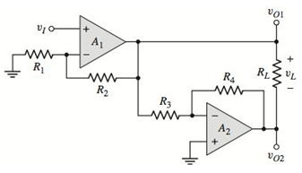
Figure P15.72
Want to see the full answer?
Check out a sample textbook solution
Chapter 15 Solutions
Microelectronics: Circuit Analysis and Design


- calculate the loop gain voltage for the circuit shown in this image given that the unity gain frequency of the LF157A is 20MHZ and output for 1kHz and 10 MHz.arrow_forwardactive band pass filter Why does the graphic appear like this in this case discuss it?arrow_forwardExplain the concept of PWM (Pulse Width Modulation) and its applications in controlling the intensity of electronic devices in microcontroller-based systems.arrow_forward
- Define modulation index. Why is it kept low? What is the role of a bandpass filter?arrow_forwardAn analog signal is to be coded by an ADC. The signal contains significant frequencies up to 6MHz. The quantization error in any one sample value must be within ± 0.5% of the peak-to-peak amplitude range of the ADC. How many binary digits must each sample contain? Apply (or equate) the formulas:Δ = Xmax - Xmin / L - 1where Xmax - Xmin = peak-to-peak amplitude range (XRange)eq[n] = Δ/2 (maximum quantization noise)eq[n] = 0.005 XRangearrow_forwardWhat will be the ratio of amplitudes of largest (maximum) signal to smallest (minimum) signal to which the system is subjected? a) Time constantb) Settling periode) Dynamic ranged) Bandwidtharrow_forward
- Show and explain in detail the Mathematical Equation of Frequency Modulation (FM).arrow_forwardShow and explain in detail the Mathematical Equation of Phase Modulation (FM).arrow_forwardSolve in digital format please In your words, describe what the signal modulation process consists of.arrow_forward
- what is the magnitude gain of Low pass butterworth filter., 6th order.arrow_forwardWhat are the circumstances in which a Kalman filter should be employed?arrow_forwardA Delta modulator is used to encode a speech signal x(t) = b sin Wmt band-limited to fm = 10KHz with sampling frequency, fs-100 KHz. For b = +4-volt peak signal voltage, 1) Find the minimum step size to avoid slope overloading. 2) Calculate Signal to quantization noise ratio.arrow_forward
 Introductory Circuit Analysis (13th Edition)Electrical EngineeringISBN:9780133923605Author:Robert L. BoylestadPublisher:PEARSON
 Delmar's Standard Textbook Of ElectricityElectrical EngineeringISBN:9781337900348Author:Stephen L. HermanPublisher:Cengage Learning
 Programmable Logic ControllersElectrical EngineeringISBN:9780073373843Author:Frank D. PetruzellaPublisher:McGraw-Hill Education
 Fundamentals of Electric CircuitsElectrical EngineeringISBN:9780078028229Author:Charles K Alexander, Matthew SadikuPublisher:McGraw-Hill Education
 Electric Circuits. (11th Edition)Electrical EngineeringISBN:9780134746968Author:James W. Nilsson, Susan RiedelPublisher:PEARSON
 Engineering ElectromagneticsElectrical EngineeringISBN:9780078028151Author:Hayt, William H. (william Hart), Jr, BUCK, John A.Publisher:Mcgraw-hill Education,