
Concept explainers
Videos
(a)
To derive: The expression for the frequency of oscillation
(a)
Answer to Problem 15.30P
The expression for the frequency of oscillation is
Explanation of Solution
Given:
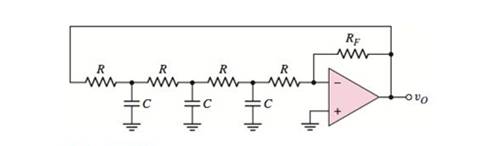
Consider the circuit shown below.

Calculation:
The non-inverting terminal of op-amp is grounded. Hence, the voltage
From virtual ground, the voltage at non-inverting terminal is equal to voltage at inverting terminal
Use KCL at the node
Use KCL at the node
Use KCL at the node
Substitute
Substitute equation (3) in equation (2),
Substitute equation (4) in equation (1),
Use KCL at the node
Substitute
Substitute
The transfer function is given by.
To find the frequency oscillation, set
From the Barkhausen criterion, the condition for oscillation is that
To satisfy the condition
Conclusion:
Therefore, the expression for the frequency of oscillation is
(b)
The condition of oscillation.
(b)
Answer to Problem 15.30P
The condition of oscillation is
Explanation of Solution
Given:
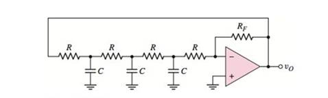
Consider the circuit shown below.
Calculation:
Substitute
The condition for oscillation is that
Substitute
Therefore, the required condition for oscillation is
Conclusion:
Therefore, the required expression for the frequency of oscillation is
(c)
To find: The values of capacitor and
(c)
Answer to Problem 15.30P
The required values are
Explanation of Solution
Given:
Consider the circuit shown below.
Calculation:
Substitute
Thus, the required feedback resistance is
Substitute
Conclusion:
Therefore, the required values are
Want to see more full solutions like this?
Chapter 15 Solutions
Microelectronics: Circuit Analysis and Design


- If a positive change in modulation signal level of 200 mV will cause a positive frequency deviation of 10 kHz, what I be the frequency deviation for a negative change of 100 mV in the level of the modulating signals? (Ans:-5kHz)arrow_forwarda.Derive the excitation equations b. Determine transition and output equations c. Derive the transition/output table and Draw the state diagram.arrow_forwardC ompare the amplitude modullation and frequency modulations. What arethe advantages and disadvantages of both systems? (Please original answer not copy from internet)arrow_forward
- Figure Q.4(c) shows a Schmitt Trigger circuit. Assuming that the output will saturate at ±Vsat = ±12 V and Vi = 8 sin wt [V],(i) Derive the expression for VUTP and VLTP.(ii) Draw and label the output signal, Vo.(iii) Draw and label the transfer characteristic, Vo vs Vi.arrow_forwardA modem (modulator-demodulator) converts digital data to analog signal. There are 3 ways to modulate a digital signal on an analog carrier signal. How that ways will work when amplitude frequency carries 0 and 1. Describe all possible ways.arrow_forwardDetermine modulation index for a frequency modulator with a deviation sensitivity of 20 kHz/V and a modulating signal of 5cos 2π(2500)tarrow_forward
- FIR and IIR filters: merits and disadvantages in digital signal processing?arrow_forwardShow and explain in detail the Mathematical Equation of Frequency Modulation (FM).arrow_forwardDraw a block diagram of a simple amplitude modulation. Explain briefly how amplitude modulation is achieved.arrow_forward
- Explain the concept of PWM (Pulse Width Modulation) and its applications in controlling the intensity of electronic devices in microcontroller-based systems.arrow_forwardWhat is the use of pulse amplitude modulation and pulse position modulation compared with pulse code modulation?arrow_forwardwhat is the magnitude gain of Low pass butterworth filter., 6th order.arrow_forward
 Introductory Circuit Analysis (13th Edition)Electrical EngineeringISBN:9780133923605Author:Robert L. BoylestadPublisher:PEARSON
 Delmar's Standard Textbook Of ElectricityElectrical EngineeringISBN:9781337900348Author:Stephen L. HermanPublisher:Cengage Learning
 Programmable Logic ControllersElectrical EngineeringISBN:9780073373843Author:Frank D. PetruzellaPublisher:McGraw-Hill Education
 Fundamentals of Electric CircuitsElectrical EngineeringISBN:9780078028229Author:Charles K Alexander, Matthew SadikuPublisher:McGraw-Hill Education
 Electric Circuits. (11th Edition)Electrical EngineeringISBN:9780134746968Author:James W. Nilsson, Susan RiedelPublisher:PEARSON
 Engineering ElectromagneticsElectrical EngineeringISBN:9780078028151Author:Hayt, William H. (william Hart), Jr, BUCK, John A.Publisher:Mcgraw-hill Education,