
a.
The expression for the frequency of the oscillation.
a.
Answer to Problem 15.29P
The expression for the frequency of oscillation:
Explanation of Solution
Given:
The circuit is given as:
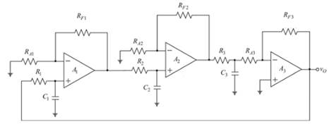
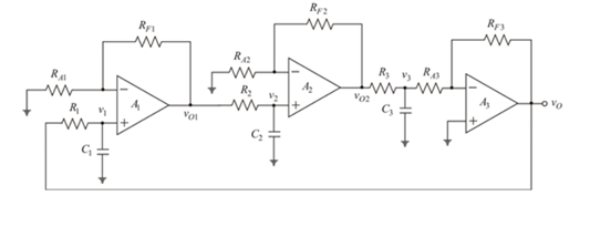
The circuit is redrawn by labeling the voltages as shown below:
Assuming:
Considering
Nodal analysis at the node
The amplifier gain of
Now, the output of
The nodal analysis at the node
Applying the nodal analysis at the inverting terminal of the
Solving equation (3):
Now, solving the equation (1):
Evaluating the frequency of the oscillation, use
Now, equating the imaginary values to 0:
Squaring the both sides:
Hence, the needed expression for the frequency of oscillation:
b.
The condition for the oscillation.
b.
Answer to Problem 15.29P
The condition for oscillation:
Explanation of Solution
Given:
The circuit is given as:
When,
The condition for oscillation:
Taking
Hence, the needed condition for oscillation:
c.
The condition for the oscillation.
c.
Answer to Problem 15.29P
The condition for oscillation:
Explanation of Solution
Given:
The circuit is given as:

Now substituting the values in equation 4:
Hence, the condition for the oscillation:
Want to see more full solutions like this?
Chapter 15 Solutions
MICROELECT. CIRCUIT ANALYSIS&DESIGN (LL)

- Find oscillator gain (Av)?arrow_forwardDesign & draw different practical circuits that can be generating a pulse position modulated signal? Discuss the meaning of synchronization & how we can implement it in pulse timing modulation?arrow_forwardQ1. Design asynchronous (ripple ) binary counter and timing diagram for the following sequence (0,1,2,3,4,5) Q2. Determine the resolution expressed as a percentage of 16-bit DAC.arrow_forward
- A Data Acquisiton system is used for sensing angular speed with an analog DC Tachometer with asensitivity of 0.05 volt/rpm. The ADC of the system is a 8 bit component and has a full scale of 10V. If the output ofDAC is 101, what is the possible angular speed range?arrow_forward2a. Assume a digital to analog conversion system uses a 10-bit integerto represent an analog temperature over a range of -25oF to 125oIf the actual temperature being read was 65.325oF, what would bethe closest possible value that the system could represent? 2b. What is the minimum sampling rate needed in order to successfullycapture frequencies up to 155 KHz in an analog signal?arrow_forwardQ1.A) If an 8-bit SAR ADC is used to digitize 8V full scale signal, what will be the digital o/p for an analog i/p of 5.76 V (perform complete analysis)?arrow_forward
- Explain the functions of decoders and multiplexers. Then given at least two examples of applications for both of them.arrow_forwardWhat do you mean by fractional sampling rate conversion? Explain with an example of converting 48 kHz signal to 44.1 kHz signal using multi-stage fractional sampling rate converterarrow_forwardExplain by block diagram and equations the PLL method of Demodulating FMarrow_forward
- What are the advantages of using Digital Signal Processing in audio systems?arrow_forwardExplain the concept of motherboard VRMs (Voltage Regulator Modules) and their role in power delivery to the CPU. Discuss the impact of VRM quality on system stability and performance.arrow_forwardQuestion 1: Design an analog pulse-width modulated (PWM) signal generator in order to drive a servo motor. What is the definition of modulation and what are pulse-width, pulse-position and pulse-density modulations?arrow_forward
 Introductory Circuit Analysis (13th Edition)Electrical EngineeringISBN:9780133923605Author:Robert L. BoylestadPublisher:PEARSON
 Delmar's Standard Textbook Of ElectricityElectrical EngineeringISBN:9781337900348Author:Stephen L. HermanPublisher:Cengage Learning
 Programmable Logic ControllersElectrical EngineeringISBN:9780073373843Author:Frank D. PetruzellaPublisher:McGraw-Hill Education
 Fundamentals of Electric CircuitsElectrical EngineeringISBN:9780078028229Author:Charles K Alexander, Matthew SadikuPublisher:McGraw-Hill Education
 Electric Circuits. (11th Edition)Electrical EngineeringISBN:9780134746968Author:James W. Nilsson, Susan RiedelPublisher:PEARSON
 Engineering ElectromagneticsElectrical EngineeringISBN:9780078028151Author:Hayt, William H. (william Hart), Jr, BUCK, John A.Publisher:Mcgraw-hill Education,