
MICROELECT. CIRCUIT ANALYSIS&DESIGN (LL)
4th Edition
ISBN: 9781266368622
Author: NEAMEN
Publisher: MCG
expand_more
expand_more
format_list_bulleted
Concept explainers
Videos
Textbook Question
Chapter 15, Problem 15.60P
The saturated output voltages of the comparator in Figure P15.60 are± 10 V. (a) Find
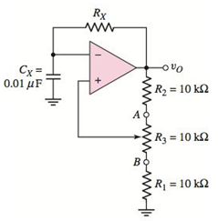
Figure P15.60
Expert Solution & Answer
Want to see the full answer?
Check out a sample textbook solution
Students have asked these similar questions
a) Design a Schmitt Trigger, draw the circuit diagram for the following condition.
VUT = 3.5 Volts; VLT =-3.5 Volts. Vi = 9 Sin ot. Draw the output waveform.
b) Design a Multi-vibrator circuit to generate square wave with 10 KHz frequency.
2. For the circuit in Figure 15,
b. What change would you expect in the output if the DC voltage is reversed?
-4) Design a circait containing a comparater with a hy steresis loop
a. Draw the circuit with all values of the components required for the dksign.
b. What is the name of the circuit in (a).
c. Sketch the output waveform when the input is a 15-V peak sine wave.
d. Adjust the value of RI in the circuit such that the hysteresis width will be 10.
Chapter 15 Solutions
MICROELECT. CIRCUIT ANALYSIS&DESIGN (LL)
Ch. 15 - Design a twopole lowpass Butterworth filter with a...Ch. 15 - Consider the switchedcapacitor circuit in Figure...Ch. 15 - Prob. 15.3EPCh. 15 - (a) Design a threepole highpass Butterworth active...Ch. 15 - Prob. 15.2TYUCh. 15 - Prob. 15.3TYUCh. 15 - Simulate a 25M resistance using the circuit in...Ch. 15 - Design the phaseshift oscillator shown in Figure...Ch. 15 - Design the Wienbridge circuit in Figure 15.17 to...Ch. 15 - Prob. 15.5TYU
Ch. 15 - Prob. 15.6TYUCh. 15 - Prob. 15.6EPCh. 15 - Redesign the street light control circuit shown in...Ch. 15 - A noninverting Schmitt trigger is shown m Figure...Ch. 15 - For the Schmitt trigger in Figure 15.30(a), the...Ch. 15 - Prob. 15.9TYUCh. 15 - Prob. 15.8EPCh. 15 - Prob. 15.9EPCh. 15 - Consider the 555 IC monostablemultivibrator. (a)...Ch. 15 - The 555 IC is connected as an...Ch. 15 - Prob. 15.10TYUCh. 15 - Prob. 15.11TYUCh. 15 - Prob. 15.12TYUCh. 15 - Prob. 15.12EPCh. 15 - Prob. 15.13EPCh. 15 - (a) Consider the bridge amplifier in Figure 15.46...Ch. 15 - Prob. 15.14EPCh. 15 - Prob. 15.15EPCh. 15 - Prob. 15.16EPCh. 15 - Prob. 1RQCh. 15 - Prob. 2RQCh. 15 - Consider a lowpass filter. What is the slope of...Ch. 15 - Prob. 4RQCh. 15 - Describe how a capacitor in conjunction with two...Ch. 15 - Sketch a onepole lowpass switchedcapacitor filter...Ch. 15 - Explain the two basic principles that must be...Ch. 15 - Prob. 8RQCh. 15 - Prob. 9RQCh. 15 - Prob. 10RQCh. 15 - Prob. 11RQCh. 15 - What is the primary advantage of a Schmitt trigger...Ch. 15 - Sketch the circuit and explain the operation of a...Ch. 15 - Prob. 14RQCh. 15 - Prob. 15RQCh. 15 - Prob. 16RQCh. 15 - Prob. 17RQCh. 15 - Prob. 18RQCh. 15 - Prob. D15.1PCh. 15 - Prob. 15.2PCh. 15 - The specification in a highpass Butterworth filter...Ch. 15 - (a) Design a twopole highpass Butterworth active...Ch. 15 - (a) Design a threepole lowpass Butterworth active...Ch. 15 - Prob. 15.6PCh. 15 - Prob. 15.7PCh. 15 - Prob. 15.8PCh. 15 - A lowpass filter is to be designed to pass...Ch. 15 - Prob. 15.10PCh. 15 - Prob. 15.11PCh. 15 - Prob. D15.12PCh. 15 - Prob. D15.13PCh. 15 - Prob. D15.14PCh. 15 - Prob. 15.15PCh. 15 - Prob. 15.16PCh. 15 - Prob. 15.17PCh. 15 - Prob. 15.18PCh. 15 - A simple bandpass filter can be designed by...Ch. 15 - Prob. 15.20PCh. 15 - Prob. 15.21PCh. 15 - Prob. D15.22PCh. 15 - Prob. 15.23PCh. 15 - Consider the phase shift oscillator in Figure...Ch. 15 - In the phaseshift oscillator in Figure 15.15, the...Ch. 15 - Consider the phase shift oscillator in Figure...Ch. 15 - Prob. 15.27PCh. 15 - Prob. 15.28PCh. 15 - Prob. 15.29PCh. 15 - Prob. 15.30PCh. 15 - Prob. 15.31PCh. 15 - A Wienbridge oscillator is shown in Figure P15.32....Ch. 15 - Prob. 15.33PCh. 15 - Prob. D15.34PCh. 15 - Prob. D15.35PCh. 15 - Prob. 15.36PCh. 15 - Prob. 15.37PCh. 15 - Prob. D15.38PCh. 15 - Prob. 15.39PCh. 15 - Prob. 15.40PCh. 15 - Prob. 15.41PCh. 15 - For the comparator in the circuit in Figure...Ch. 15 - Prob. 15.43PCh. 15 - Prob. 15.44PCh. 15 - Prob. 15.45PCh. 15 - Consider the Schmitt trigger in Figure P15.46....Ch. 15 - The saturated output voltages are VP for the...Ch. 15 - Consider the Schmitt trigger in Figure 15.30(a)....Ch. 15 - Prob. 15.50PCh. 15 - Prob. 15.52PCh. 15 - Prob. 15.53PCh. 15 - Prob. 15.54PCh. 15 - Prob. 15.55PCh. 15 - Prob. 15.56PCh. 15 - Prob. 15.57PCh. 15 - Prob. D15.58PCh. 15 - Prob. 15.59PCh. 15 - The saturated output voltages of the comparator in...Ch. 15 - (a) The monostablemultivibrator in Figure 15.37 is...Ch. 15 - A monostablemultivibrator is shown in Figure...Ch. 15 - Prob. D15.63PCh. 15 - Design a 555 monostablemultivibrator to provide a...Ch. 15 - Prob. 15.65PCh. 15 - Prob. 15.66PCh. 15 - Prob. 15.67PCh. 15 - Prob. 15.68PCh. 15 - An LM380 must deliver ac power to a 10 load. The...Ch. 15 - Prob. 15.70PCh. 15 - Prob. D15.71PCh. 15 - Prob. 15.72PCh. 15 - (a) Design the circuit shown in Figure P15.72 such...Ch. 15 - Prob. 15.74PCh. 15 - Prob. 15.75PCh. 15 - Prob. 15.76PCh. 15 - Prob. D15.77PCh. 15 - Prob. 15.78P
Knowledge Booster


Learn more about
Need a deep-dive on the concept behind this application? Look no further. Learn more about this topic, electrical-engineering and related others by exploring similar questions and additional content below.Similar questions
- A chopper has input voltage of 290 and the load resistance as 50, the average load current as 50A. If the non-conducting time of thyristor chopper is 120 Usec. Calculate the pulse width of output voltage in U sec. In case pulse width is 1/3rd for constant frequency operation, find new output voltage. Duty Cycle pulse width of output voltage in usec new output voltagearrow_forwardAn RL load (R=0.2 Ohms, L=10 mH) is controlled by a converter. The supply voltage Vs is 600V and the chopper frequency is 200 Hz. The maximum peak to peak ripple current is equal to: Select one: a. 30A b. 55A c. 90A d. 75Aarrow_forward6. Refer to the RC Phase-shift Oscillator below. A Vin R₁ + Rf 6.a. Derive the feedback factor formula for this circuit. 6.b. Draw the output waveform. C C mm C Vout wwwwwarrow_forward
- A full-wave rectifier produces a 32V peak rectified voltage from a 50Hz ac source. Determine the filter capacitor needed to provide a DC output voltage 24V across a 500 ohm load.arrow_forwardA chopper has input voltage of 290 and the load resistance as 50. the average load current as 50A. If the non-conducting time of thyristor chopper is 120 µ sec. Calculate the pulse width of output voltage in usec. In case pulse width is 1/3rd for constant frequency operation, find new output voltage. Duty Cycle pulse width of output voltage in sec new output voltagearrow_forwardProblem: If the no-load output voltage of a regulator is 15.5 V and the full-load output is 14.9 V, what is the percent load regulation?arrow_forward
- Non Linear Wave S... Non Linear Wave Shaping (clipper, clamper) circuits Clipper circuit: Vi (p-p)= 10 volt (Sinewave) F=1 kHz R= 10 Kohm V= 4 volt Find and Sketch the output signal for the clipper circuit. Clamper circuit: Vi (p-p)= 10 volt (Sinewave) F=1 kHz R= 10 Kohm V= 4 volt C= 1 micro F Find and analysis of and Sketch the output signal for the clamper circuit.arrow_forwardin a given figure, a signal is shown on a CRO screen. The CRO voltage per division (Volt/Div.) knob is set on 5 V, and Time per Division (Time/Div) knob is set on 10 ms. Calculate the signal amplitude and frequency. THEICN Ground LEVE NTENS TRO NP FOCUS VO ON INVERT NVERT CHI 40arrow_forwardA clamping circuit has to have an independent source, a diode, a resistor, and a capacitor. To keep a constant voltage on the capacitor over the period of the input, the RC time constant must be large. A design rule of thumb is to make the RC time constant at least five times the half period of the input signal. Why do we need to make the RC time constant at least five times the half period of the input signal greater? Is having a 2, 3, or 4 times RC time constant, not enough?arrow_forward
- Problem: If the no-load output voltage of a regulator is 15.5 V and the full-load output is 14.9 V, what is the percent load regulation? Express the numerical values up to 2 decimal places.arrow_forwardThe main function of a boost converter is to: A. Step up or down the input voltage B. Step up the input voltage C. Step down the voltage D. Keep the converter in continuous conduction modearrow_forwardB- An rate. analog signal having single frequency as 3 kHz is sampled with 5 kHz S Describe its frequency spectrum. What will be the output if the sampled signals a passed through a low-pass filter having cutoff frequency at 2.5 kHz? signal. are sent in the analogarrow_forward
arrow_back_ios
SEE MORE QUESTIONS
arrow_forward_ios
Recommended textbooks for you
 Introductory Circuit Analysis (13th Edition)Electrical EngineeringISBN:9780133923605Author:Robert L. BoylestadPublisher:PEARSON
 Delmar's Standard Textbook Of ElectricityElectrical EngineeringISBN:9781337900348Author:Stephen L. HermanPublisher:Cengage Learning
 Programmable Logic ControllersElectrical EngineeringISBN:9780073373843Author:Frank D. PetruzellaPublisher:McGraw-Hill Education
 Fundamentals of Electric CircuitsElectrical EngineeringISBN:9780078028229Author:Charles K Alexander, Matthew SadikuPublisher:McGraw-Hill Education
 Electric Circuits. (11th Edition)Electrical EngineeringISBN:9780134746968Author:James W. Nilsson, Susan RiedelPublisher:PEARSON
 Engineering ElectromagneticsElectrical EngineeringISBN:9780078028151Author:Hayt, William H. (william Hart), Jr, BUCK, John A.Publisher:Mcgraw-hill Education,
Introductory Circuit Analysis (13th Edition)
Electrical Engineering
ISBN:9780133923605
Author:Robert L. Boylestad
Publisher:PEARSON
Delmar's Standard Textbook Of Electricity
Electrical Engineering
ISBN:9781337900348
Author:Stephen L. Herman
Publisher:Cengage Learning
Programmable Logic Controllers
Electrical Engineering
ISBN:9780073373843
Author:Frank D. Petruzella
Publisher:McGraw-Hill Education
Fundamentals of Electric Circuits
Electrical Engineering
ISBN:9780078028229
Author:Charles K Alexander, Matthew Sadiku
Publisher:McGraw-Hill Education
Electric Circuits. (11th Edition)
Electrical Engineering
ISBN:9780134746968
Author:James W. Nilsson, Susan Riedel
Publisher:PEARSON
Engineering Electromagnetics
Electrical Engineering
ISBN:9780078028151
Author:Hayt, William H. (william Hart), Jr, BUCK, John A.
Publisher:Mcgraw-hill Education,
Understanding Frequency Modulation; Author: Rohde Schwarz;https://www.youtube.com/watch?v=gFu7-7lUGDg;License: Standard Youtube License