
Concept explainers
a.
The expression for the frequency of the oscillation in the terms of C, R and Rv.
a.
Answer to Problem 15.31P
The frequency of oscillation:
Explanation of Solution
Given:
The circuit is given for the phase shift oscillator:
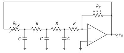
Redrawing the given circuit
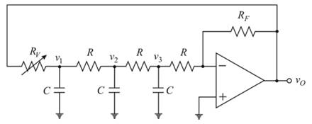
Nodal analysis at the node
Nodal analysis at the node
Nodal analysis at the node
Now, solving the equation 2 and 3:
Nodal analysis at the inverting terminal:
From equation (3):
From equation 4:
Substituting values of
Now simplifying more:
Now equating imaginary part to 0:
Now simplifying:
Squaring on the both sides:
Since, the frequency is given as:
Hence, the required frequency of oscillation is
b.
The range in the frequency of the oscillation.
b.
Answer to Problem 15.31P
The range of frequency of oscillation:
Explanation of Solution
Given:
The circuit is given for the phase shift oscillator:

The expression for the frequency of the oscillation is given as:
Substitute the known values in the above expression:
More simplifying:
If,
Substitute the known values:
More simplifying:
Hence, the required range of frequency of oscillation:
Want to see more full solutions like this?
Chapter 15 Solutions
MICROELECT. CIRCUIT ANALYSIS&DESIGN (LL)


- TOPIC: AMPLITUDE MODULATION AND DEMODULATIONPlease answer this 2 question thanks.1. What is the different degree of modulation?2. What are the limitations of square law modulator?arrow_forwardShow and explain in detail the Mathematical Equation of Frequency Modulation (FM).arrow_forwardWhat Is frequency modulation and demodulation? Describe their importance and how they work.arrow_forward
- What are the circumstances in which a Kalman filter should be employed?arrow_forwardIf a positive change in modulation signal level of 200 mV will cause a positive frequency deviation of 10 kHz, what I be the frequency deviation for a negative change of 100 mV in the level of the modulating signals? (Ans:-5kHz)arrow_forwardDetermine the value of RF necessary for the three stage RC phase-shift to operate as a stable and sustained oscillator with R=10Kohm, and C=0.003µf. determine the frequency of oscillation, design the final circuit of phase-shift.arrow_forward
- Good day! Question: What is the importance of Modulator and Demodulator (functions) in FM.arrow_forwarddetermine voltaeg gainarrow_forwardcalculate the loop gain voltage for the circuit shown in this image given that the unity gain frequency of the LF157A is 20MHZ and output for 1kHz and 10 MHz.arrow_forward
- Q) What is the need of amplitude modulation?arrow_forwardAn analog signal is to be coded by an ADC. The signal contains significant frequencies up to 6MHz. The quantization error in any one sample value must be within ± 0.5% of the peak-to-peak amplitude range of the ADC. How many binary digits must each sample contain? Apply (or equate) the formulas:Δ = Xmax - Xmin / L - 1where Xmax - Xmin = peak-to-peak amplitude range (XRange)eq[n] = Δ/2 (maximum quantization noise)eq[n] = 0.005 XRangearrow_forward3) For the given circuit;→Setup state thetransition table →Sketch state thesatate transitiondiagram→Derive the stateequationsarrow_forward
 Introductory Circuit Analysis (13th Edition)Electrical EngineeringISBN:9780133923605Author:Robert L. BoylestadPublisher:PEARSON
 Delmar's Standard Textbook Of ElectricityElectrical EngineeringISBN:9781337900348Author:Stephen L. HermanPublisher:Cengage Learning
 Programmable Logic ControllersElectrical EngineeringISBN:9780073373843Author:Frank D. PetruzellaPublisher:McGraw-Hill Education
 Fundamentals of Electric CircuitsElectrical EngineeringISBN:9780078028229Author:Charles K Alexander, Matthew SadikuPublisher:McGraw-Hill Education
 Electric Circuits. (11th Edition)Electrical EngineeringISBN:9780134746968Author:James W. Nilsson, Susan RiedelPublisher:PEARSON
 Engineering ElectromagneticsElectrical EngineeringISBN:9780078028151Author:Hayt, William H. (william Hart), Jr, BUCK, John A.Publisher:Mcgraw-hill Education,