
Applied Statics and Strength of Materials (6th Edition)
6th Edition
ISBN: 9780133840728
Author: Limbrunner
Publisher: PEARSON
expand_more
expand_more
format_list_bulleted
Concept explainers
Videos
Textbook Question
Chapter 15, Problem 15.39P
For Problems 15.31 through 15.43, use the moment-area method.
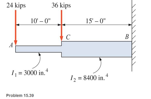
15.39 For the steel beam shown, calculate the slope at the free end and the maximum deflection. Note the varying moment of inertia.
Expert Solution & Answer
Want to see the full answer?
Check out a sample textbook solution
Students have asked these similar questions
solve for the formulas of the maximum slope, maximum deflection, and their respective location, for the beams
Draw the SFD and BMD for the beams loaded as shown in FigCalculate the position and magnitude of maximum bending moment and locate points of contra-flexures if any.
answers must tally with those provided
Draw the shear and bending moment diagrams and the qualitative deflected shape for the beam shown
Chapter 15 Solutions
Applied Statics and Strength of Materials (6th Edition)
Ch. 15 - A 14 in.-diameter aluminum rod is bent into a...Ch. 15 - 15.2 Calculate the maximum bending stress produced...Ch. 15 - A 500 -mm-long steel bar having a cross section of...Ch. 15 - 15.4 An aluminum wire has a diameter of in....Ch. 15 - 15.5 A -in.-wide by in.-thick board is bent to a...Ch. 15 - 15.6 A Douglas fir beam is in. wide and in. deep....Ch. 15 - Prob. 15.7PCh. 15 - For Problems 15.7 through 15.14, use the formula...Ch. 15 - For Problems 15.7 through 15.14, use the formula...Ch. 15 - For Problems 15.7 through 15.14, use the formula...
Ch. 15 - For Problems 15.7 through 15.14, use the formula...Ch. 15 - For Problems 15.7 through 15.I4, use the formula...Ch. 15 - For Problems 15.7 through 15.14, use the formula...Ch. 15 - For Problems 15.7 through 15.14, use the formula...Ch. 15 - For Problems 15.15 through 15.26, use the...Ch. 15 - For Problems 15.15 through 15.26, use the...Ch. 15 - For Problems 15.15 through 15.26, use the...Ch. 15 - For Problems 15.15 through 15.26, use the...Ch. 15 - For Problems 15.15 through 15.26, use the...Ch. 15 - For Problems 15.15 through 15.26, use the...Ch. 15 - For Problems 15.15 through 15.26, use the...Ch. 15 - For Problems 15.15 through 15.26, use the...Ch. 15 - For Problems 15.15 through 15.26, use the...Ch. 15 - For Problems 15.15 through 15.26, use the...Ch. 15 - For Problems 15.15 through 15.26, use the...Ch. 15 - For Problems 15.15 through 15.26, use the...Ch. 15 - 15.27 Draw the moment diagram by parts for the...Ch. 15 - 15.28 Draw the moment diagram by parts for the...Ch. 15 - 15.29 Draw the moment diagram by parts for the...Ch. 15 - 15.30 For the beam shown, draw the conventional...Ch. 15 - For Problems 15.31 through 15.43, use the...Ch. 15 - For Problems 15.31 through 15.43, use the...Ch. 15 - For Problems 15.31 through 15.43, use the...Ch. 15 - For Problems 15.31 through 15.43, use the...Ch. 15 - For Problems 15.31 through 15.43, use the...Ch. 15 - For Problems 15.31 through 15.43, use the...Ch. 15 - For Problems 15.31 through 15.43, use the...Ch. 15 - For Problems 15.31 through 15.43, use the...Ch. 15 - For Problems 15.31 through 15.43, use the...Ch. 15 - For Problems 15.31 through 15.43, use the...Ch. 15 - For Problems 15.31 through 15.43, use the...Ch. 15 - For Problems 15.31 through 15.43, use the...Ch. 15 - For Problems 15.31 through 15.43, use the...Ch. 15 - 15.49 If the elastic limit of a steel wire is...Ch. 15 - 15.50 Calculate the bending moment required to...Ch. 15 - 15.51 A 6-ft-long cantilever beam is subjected to...Ch. 15 - 15.52 A structural steel wide-flange section is...Ch. 15 - 15.53 A simply supported structural steel...Ch. 15 - 15.54 A structural steel wide-flange shape is...Ch. 15 - A solid, round simply supported steel shaft is...Ch. 15 - Using the moment-area method, check the...Ch. 15 - 15.57 A 1-in.-diameter steel bar is 25 ft long and...Ch. 15 - 15.58 A 102-mm nominal diameter standard-weight...Ch. 15 - I 5.59 Compute the maximum deflection for the...Ch. 15 - An 8-in-wide by 12-in-deep redwood timber beam...Ch. 15 - 15.61 A solid steel shaft 3 in. in diameter and 20...Ch. 15 - 15.62 For the beam shown, draw the conventional...Ch. 15 - 15.63 Rework Problem 15.62 with concentrated loads...Ch. 15 - 15.64 A solid steel shaft 3 in. in diameter and 20...Ch. 15 - 15.65 A structural steel wide-flange section is...Ch. 15 - 15.66 A 6-in.-by-10-in, hem-fir timber beam (S4S)...Ch. 15 - 15.67 A simply supported structural steel...Ch. 15 - Calculate the maximum permissible span length for...Ch. 15 - 15.69 A structural steel wide-flange section 10 ft...Ch. 15 - 15.70 A structural steel wide-flange section...Ch. 15 - 15.71 Determine the deflection at point C and...Ch. 15 - 15.72 Calculate the deflection midway between the...Ch. 15 - 15.73 Derive an expression for the maximum...Ch. 15 - 15.74 Derive an expression for the maximum...
Knowledge Booster


Learn more about
Need a deep-dive on the concept behind this application? Look no further. Learn more about this topic, mechanical-engineering and related others by exploring similar questions and additional content below.Similar questions
- Compute the midspan value of EIy for the beam loaded as shown.arrow_forwardA cantilever beam shown carries a concentrated load of 20 kN at point C. Assume constant value of E. Compute the deflection at C. Compute the slope at C. Compute the deflection at B.arrow_forward6.38 Compute the value of EId at the right end of the cantilever beam.arrow_forward
- A beam with the cross-section shown is carrying a bending moment of M. Calculate the maximum bending stress (σ) in the beam.arrow_forwardFind the value of the maximum deflection of each beam.arrow_forwardDetermine the reactions and draw the shear and bending moment diagrams for the beams shown but using slope deflection methodarrow_forward
- draw a shear and bending moment diagram for the beam shown. Label each diagram with values at locations, minimums and maximuns, changes in slope and where it crosses zeroarrow_forwardBy using three moment equation, determine the deflection three meters to the left of roller supportarrow_forwardFor the prismatic beam and load shown in fig. determine the slope and deflection at point Darrow_forward
arrow_back_ios
arrow_forward_ios
Recommended textbooks for you
 Elements Of ElectromagneticsMechanical EngineeringISBN:9780190698614Author:Sadiku, Matthew N. O.Publisher:Oxford University Press
 Mechanics of Materials (10th Edition)Mechanical EngineeringISBN:9780134319650Author:Russell C. HibbelerPublisher:PEARSON
 Thermodynamics: An Engineering ApproachMechanical EngineeringISBN:9781259822674Author:Yunus A. Cengel Dr., Michael A. BolesPublisher:McGraw-Hill Education
 Control Systems EngineeringMechanical EngineeringISBN:9781118170519Author:Norman S. NisePublisher:WILEY
 Mechanics of Materials (MindTap Course List)Mechanical EngineeringISBN:9781337093347Author:Barry J. Goodno, James M. GerePublisher:Cengage Learning
 Engineering Mechanics: StaticsMechanical EngineeringISBN:9781118807330Author:James L. Meriam, L. G. Kraige, J. N. BoltonPublisher:WILEY
Elements Of Electromagnetics
Mechanical Engineering
ISBN:9780190698614
Author:Sadiku, Matthew N. O.
Publisher:Oxford University Press
Mechanics of Materials (10th Edition)
Mechanical Engineering
ISBN:9780134319650
Author:Russell C. Hibbeler
Publisher:PEARSON
Thermodynamics: An Engineering Approach
Mechanical Engineering
ISBN:9781259822674
Author:Yunus A. Cengel Dr., Michael A. Boles
Publisher:McGraw-Hill Education
Control Systems Engineering
Mechanical Engineering
ISBN:9781118170519
Author:Norman S. Nise
Publisher:WILEY
Mechanics of Materials (MindTap Course List)
Mechanical Engineering
ISBN:9781337093347
Author:Barry J. Goodno, James M. Gere
Publisher:Cengage Learning
Engineering Mechanics: Statics
Mechanical Engineering
ISBN:9781118807330
Author:James L. Meriam, L. G. Kraige, J. N. Bolton
Publisher:WILEY
Solids: Lesson 53 - Slope and Deflection of Beams Intro; Author: Jeff Hanson;https://www.youtube.com/watch?v=I7lTq68JRmY;License: Standard YouTube License, CC-BY