
Concept explainers
Videos
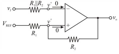
Consider the Schmitt trigger in Figure 15.30(a). (a) Derive the expressionfor the switching point and crossover voltages as given in Equations (15.76)and (15.77). (b) Let
(a)
To derive: the expression for the switching point and crossover voltages
Answer to Problem 15.49P
The switching voltage
The upper crossover voltage of Schmitt trigger is
The lower crossover voltage of Schmitt trigger is
Explanation of Solution
Given:
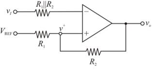
Consider the Schmitt trigger as shown below.

Calculation:
In an ideal op-amp, the inverting and non-inverting terminal currents are zero. And the inverting and non-inverting node voltages are equal. Given circuit can be represented as
Applying Kirchhoff’s current law at inverting node:
Applying Kirchhoff’s current law at non-inverting node:
Assuming
Therefore, the switching voltage
When
The upper crossover voltage off Schmitt trigger is
Therefore, the upper crossover voltage of Schmitt trigger is
When
The lower cross over voltage of Schmitt trigger is
Therefore, the lower crossover voltage of Schmitt trigger is
Conclusion:
The switching voltage
The upper crossover voltage of Schmitt trigger is
The lower crossover voltage of Schmitt trigger is
(b)
The values of
Answer to Problem 15.49P
The resistor values are
The reference voltage is
Explanation of Solution
Given:
The crossover voltages are
The minimum resistance is to be

Calculation:
Let
The minimum resistance is to be
The crossover voltages are
Substitute
Substitute
Substitute
Choose
Therefore, the resistor values are
Substitute
Substitute
Conclusion:
Therefore, the resistor values are
(c)
To find: the currents in the resistors when
Answer to Problem 15.49P
When
When
Explanation of Solution
Given:
Consider the Schmitt trigger as shown below.
Calculation:
The current in the resistor is given by
( i ) When
The current in the resistor is
Therefore, the current is
( ii ) When
The current in the resistor is
Therefore, the current is
Conclusion:
Therefore,
When
When
Want to see more full solutions like this?
Chapter 15 Solutions
Microelectronics: Circuit Analysis and Design


- Discuss the ff. topics in outline form 1.Methods of generating SSB (include the block diagram) Filter method Phase shift method Weaver method 2. Block diagram and difference of Low level modulation and high level modulation 3. Low level modulator: circuit diagram and operation Diode modulator Transistor modulator 4. High level modulator: circuit diagram and operation Collector modulatorarrow_forwardWhat are the benefits of SSBSC modulation compared to DSBFC-AM and DSBSC-AM?arrow_forwardDefine the following terms for FSK modulation: frequency deviation, modulation index, and deviation ratio.arrow_forward
- Describe the importance of using Bandpass filters in BFSK noncoherent demodulator.arrow_forwardWhat are the circumstances in which a Kalman filter should be employed?arrow_forwardcalculate the loop gain voltage for the circuit shown in this image given that the unity gain frequency of the LF157A is 20MHZ and output for 1kHz and 10 MHz.arrow_forward
- Discuss the concept of multiplexing and its importance in optimizing bandwidth utilization.arrow_forwardC ompare the amplitude modullation and frequency modulations. What arethe advantages and disadvantages of both systems? (Please original answer not copy from internet)arrow_forwardactive band pass filter Why does the graphic appear like this in this case discuss it?arrow_forward
- Draw block diagram /circuit diagram of the ff. FM circuits and discuss the operation. c. RATIO DETECTORarrow_forwardWhat is the main disadvantage of linear delta modulation? What is the solution for this problem? this question from digital communication course.arrow_forward2/What are the advantages and disadvantages of a conventional AM system with respect to DSB-SC?arrow_forward
 Introductory Circuit Analysis (13th Edition)Electrical EngineeringISBN:9780133923605Author:Robert L. BoylestadPublisher:PEARSON
 Delmar's Standard Textbook Of ElectricityElectrical EngineeringISBN:9781337900348Author:Stephen L. HermanPublisher:Cengage Learning
 Programmable Logic ControllersElectrical EngineeringISBN:9780073373843Author:Frank D. PetruzellaPublisher:McGraw-Hill Education
 Fundamentals of Electric CircuitsElectrical EngineeringISBN:9780078028229Author:Charles K Alexander, Matthew SadikuPublisher:McGraw-Hill Education
 Electric Circuits. (11th Edition)Electrical EngineeringISBN:9780134746968Author:James W. Nilsson, Susan RiedelPublisher:PEARSON
 Engineering ElectromagneticsElectrical EngineeringISBN:9780078028151Author:Hayt, William H. (william Hart), Jr, BUCK, John A.Publisher:Mcgraw-hill Education,