
MECHANICS OF MATERIALS+ACCESS >IP<
LATEST Edition
ISBN: 9780134583235
Author: Pearson
Publisher: PEARSON EDUCATION (COLLEGE)
expand_more
expand_more
format_list_bulleted
Concept explainers
Videos
Textbook Question
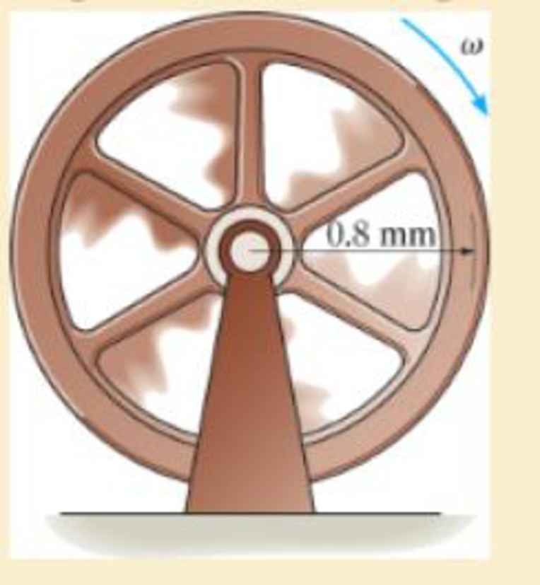
Chapter 1.5, Problem 1.67P
Determine the greatest constant angular velocity ω of the flywheel so that the average normal stress in its rim does not exceed σ = 15 MPa. Assume the rim is a thin ring having a thickness of 3 mm, width of 20 mm, and a mass of 30 kg/m. Rotation occurs in the horizontal plane. Neglect the effect of the spokes in the analysis. Hint: Consider a free-body diagram of a semicircular segment of the ring. The center of mass for this segment is located at
Expert Solution & Answer
Want to see the full answer?
Check out a sample textbook solution
Students have asked these similar questions
The solid steel shaft AC has a diameter of 25 mm and is supported by smooth bearings at D and E. It is coupled to a motor at C, which delivers 3 kW of power to the shaft while it is turning at 50 rev>s. If gears A and B remove1 kW and 2 kW, respectively, determine the maximum shear stress in the shaft within regions AB and BC. The shaft is free to turn in its support bearings D and E.
The rotating flywheel-and-shaft, when brought to a sudden stop at D, begins to oscillate clockwise-counterclockwise such that a point A on the outer edge of the flywheel is displaced through a 6-mm arc. Determine the maximum shear stress developed in the tubular A-36 steel shaft due to this oscillation. The shaft has an inner diameter of 24 mm and an outer diameter of 32 mm. The bearings at B and C allow the shaft to rotate freely, whereas the support at D holds the shaft fixed.
The 6-hp reducer motor can turn at 1200 rev>min. If the shaft has a diameter of 5 8 in., determine the maximum shear stress in the shaft.
Chapter 1 Solutions
MECHANICS OF MATERIALS+ACCESS >IP<
Ch. 1.2 - In each case, explain how to find the resultant...Ch. 1.2 - Determine the resultant internal normal force,...Ch. 1.2 - Determine the resultant internal normal force,...Ch. 1.2 - Determine the resultant internal normal force,...Ch. 1.2 - Determine the resultant internal normal force,...Ch. 1.2 - Determine the resultant internal normal force,...Ch. 1.2 - Determine the resultant internal normal force,...Ch. 1.2 - The shaft is supported by a smooth thrust bearing...Ch. 1.2 - Determine the resultant internal normal and shear...Ch. 1.2 - Determine the resultant internal loadings acting...
Ch. 1.2 - The shaft is supported by a smooth thrust bearing...Ch. 1.2 - Determine the resultant internal loadings acting...Ch. 1.2 - Determine the resultant internal loadings on the...Ch. 1.2 - Determine the resultant internal loadings at cross...Ch. 1.2 - The beam supports the distributed load shown....Ch. 1.2 - The beam supports the distributed load shown....Ch. 1.2 - The boom DF of the jib crane and the column DE...Ch. 1.2 - Determine the resultant internal loadings acting...Ch. 1.2 - Determine the resultant internal loadings acting...Ch. 1.2 - The blade of the hacksaw is subjected to a...Ch. 1.2 - The blade of the hacksaw is subjected to a...Ch. 1.2 - The beam supports the triangular distributed load...Ch. 1.2 - The beam supports the distributed load shown....Ch. 1.2 - The shaft is supported at its ends by two bearings...Ch. 1.2 - The shaft is supported at its ends by two bearings...Ch. 1.2 - The hand crank that is used in a press has the...Ch. 1.2 - Determine the resultant internal loadings acting...Ch. 1.2 - Determine the resultant internal loadings acting...Ch. 1.2 - The metal stud punch is subjected to a force of...Ch. 1.2 - Determine the resultant internal loadings acting...Ch. 1.2 - Determine the resultant internal loadings acting...Ch. 1.2 - Determine the resultant internal loadings acting...Ch. 1.2 - Determine the resultant internal loadings acting...Ch. 1.2 - The pipe has a mass of 12 kg/m. If it is fixed to...Ch. 1.2 - If the drill bit jams when the brace is subjected...Ch. 1.2 - The curved rod AD of radius r has a weight per...Ch. 1.2 - A differential element taken from a curved bar is...Ch. 1.5 - In each case, determine the largest internal shear...Ch. 1.5 - Determine the largest internal normal force in the...Ch. 1.5 - Determine the internal normal force at section A...Ch. 1.5 - The lever is held to the fixed shaft using the pin...Ch. 1.5 - The single-V butt joint transmits the force of 5...Ch. 1.5 - The uniform beam is supported by two rods AB and...Ch. 1.5 - Determine the average normal stress on the cross...Ch. 1.5 - Determine the average normal stress on the cross...Ch. 1.5 - If the 600-kN force acts through the centroid of...Ch. 1.5 - Determine the average normal stress at points A,...Ch. 1.5 - Determine the average normal stress in rod AB if...Ch. 1.5 - The supporting wheel on a scaffold is held in...Ch. 1.5 - Determine the largest intensity w of the uniform...Ch. 1.5 - The bar has a cross-sectional area A and is...Ch. 1.5 - The small block has a thickness of 0.5 in. If the...Ch. 1.5 - If the material fails when the average normal...Ch. 1.5 - If the block is subjected to a centrally applied...Ch. 1.5 - The plate has a width of 0.5 m. If the stress...Ch. 1.5 - The board is subjected to a tensile force of 200...Ch. 1.5 - The boom has a uniform weight of 600 lb and is...Ch. 1.5 - Determine the average normal stress in each of the...Ch. 1.5 - If the average normal stress in each of the...Ch. 1.5 - Determine the maximum average shear stress in pin...Ch. 1.5 - If P=5 kN, determine the average shear stress in...Ch. 1.5 - Determine the maximum magnitude P of the loads the...Ch. 1.5 - The column is made of concrete having a density of...Ch. 1.5 - The beam is supported by two rods AB and CD that...Ch. 1.5 - The beam is supported by two rods AB and CD that...Ch. 1.5 - If P = 15 kN, determine the average shear stress...Ch. 1.5 - The railcar docklight is supported by the...Ch. 1.5 - The plastic block is subjected to an axial...Ch. 1.5 - The two steel members are joined together using a...Ch. 1.5 - The bar has a cross-sectional area of 400(106) m2....Ch. 1.5 - The bar has a cross-sectional area of 400(106) m2....Ch. 1.5 - The two members used in the construction of an...Ch. 1.5 - The 2-Mg concrete pipe has a center of mass at...Ch. 1.5 - The 2-Mg concrete pipe has a center of mass at...Ch. 1.5 - The pier is made of material having a specific...Ch. 1.5 - Rods AB and BC have diameters of 4 mm and 6 mm,...Ch. 1.5 - The uniform bar, having a cross-sectional area of...Ch. 1.5 - The bar has a cross-sectional area of 400(106) m2....Ch. 1.5 - The bar has a cross-sectional area of 400(106) m2....Ch. 1.5 - The prismatic bar has a cross-sectional area A. If...Ch. 1.5 - The prismatic bar has a cross-sectional area A. If...Ch. 1.5 - The bars of the truss each have a cross-sectional...Ch. 1.5 - The bars of the truss each have a cross-sectional...Ch. 1.5 - Determine the largest load P that can be applied...Ch. 1.5 - Determine the greatest constant angular velocity ...Ch. 1.5 - The radius of the pedestal is defined by r =...Ch. 1.7 - Rods AC and BC are used to suspend the 200-kg...Ch. 1.7 - If it is subjected to double shear, determine the...Ch. 1.7 - Determine the maximum average shear stress...Ch. 1.7 - If each of the three nails has a diameter of 4 mm...Ch. 1.7 - The strut is glued to the horizontal member at...Ch. 1.7 - Determine the maximum average shear stress...Ch. 1.7 - If the eyebolt is made of a material having a...Ch. 1.7 - If the bar assembly is made of a material having a...Ch. 1.7 - Determine the maximum force P that can be applied...Ch. 1.7 - The pin is made of a material having a failure...Ch. 1.7 - If the bolt head and the supporting bracket are...Ch. 1.7 - Six nails are used to hold the hanger at A against...Ch. 1.7 - If A and B are both made of wood and are 38 in....Ch. 1.7 - Prob. 1.70PCh. 1.7 - The connection is made using a bolt and nut and...Ch. 1.7 - The tension member is fastened together using two...Ch. 1.7 - The steel swivel bushing in the elevator control...Ch. 1.7 - The spring mechanism is used as a shock absorber...Ch. 1.7 - Determine the size of square bearing plates A and...Ch. 1.7 - Determine the maximum load P that can be applied...Ch. 1.7 - Determine the required diameter of the pins at A...Ch. 1.7 - If the allowable tensile stress for wires AB and...Ch. 1.7 - If the allowable tensile stress for wires AB and...Ch. 1.7 - The cotter is used to hold the two rods together....Ch. 1.7 - Determine the required diameter of the pins at A...Ch. 1.7 - The steel pipe is supported on the circular base...Ch. 1.7 - The boom is supported by the winch cable that has...Ch. 1.7 - The boom is supported by the winch cable that has...Ch. 1.7 - The assembly consists of three disks A, B, and C...Ch. 1.7 - The two aluminum rods support the vertical force...Ch. 1.7 - The two aluminum rods AB and AC have diameters of...Ch. 1.7 - Determine the required minimum thickness t of...Ch. 1.7 - Determine the maximum allowable load P that can be...Ch. 1.7 - The compound wooden beam is connected together by...Ch. 1.7 - The hanger is supported using the rectangular pin....Ch. 1.7 - The hanger is supported using the rectangular pin....Ch. 1.7 - The rods AB and CD are made of steel. Determine...Ch. 1.7 - The aluminum bracket A is used to support the...Ch. 1.7 - If the allowable tensile stress for the bar is...Ch. 1.7 - The bar is connected to the support using a pin...Ch. 1 - The beam AB is pin supported at A and supported by...Ch. 1 - The long bolt passes through the 30-mm-thick...Ch. 1 - Determine the required thickness of member BC to...Ch. 1 - The circular punch B exerts a force of 2 kN on the...Ch. 1 - Determine the average punching shear stress the...Ch. 1 - The 150 mm by 150 mm block of aluminum supports a...Ch. 1 - The yoke-and-rod connection is subjected to a...Ch. 1 - The cable has a specific weight (weight/volume)...
Knowledge Booster


Learn more about
Need a deep-dive on the concept behind this application? Look no further. Learn more about this topic, mechanical-engineering and related others by exploring similar questions and additional content below.Similar questions
- The solid steel shaft DF has a diameter of 25 mm and is supported by smooth bearings at D and E. It is coupled to a motor at F, which delivers 12 kW of power to the shaft while it is turning at 50 rev>s. If gears A, B, and C remove3 kW, 4 kW, and 5 kW respectively, determine the maximum shear stress in the shaft within regions CF and BC. The shaft is free to turn in its support bearings D and E.arrow_forwardThe turbine develops 300 kW of power, which is transmitted to the gears such that both B and C receive an equal amount. If the rotation of the 100-mm-diameter A992 steel shaft is v = 600 rev>min., determine the absolute maximum shear stress in the shaft and the rotation of end D of the shaft relative to A. The journal bearing at D allows the shaft to turn freely about its axis.arrow_forwardThe gear motor can develop 14 hp when it turns at 600 rev>min. If the shaft has a diameter of 12 in., determine the maximum shear stress in the shaft.arrow_forward
- The uniform bar, having a cross-sectional area of A and mass per unit length of m, is pinned at its center. If it is rotating in the horizontal plane at a constant angular rate of v, determine the average normal stress in the bar as a function of x.arrow_forwardThe drill pipe has an outer diameter of 75mm, a wall thickness of 10mm, and a weight of 70 kg/m. If it is subjected to a torque and axial load as shown, determine at a point on its outer surface at section a (a) the principal stress and planes and (b) the maximum in-plane shear stress, average stress and its plane.arrow_forwardThe observation cage C has a weight of 250 kip and through a system of gears, travels upward at constant velocity along the A-36 steel column, which has a height of 200 ft. The column has an outer diameter of 3 ft and is made from steel plate having a thickness of 0.25 in. Neglect the weight of the column, and determine the average normal stress in the column at its base, B, as a function of the cage’s position y. Also, determine the displacement of end A as a function of y.arrow_forward
- A cylinder having the dimensions shown is made from magnesium Am 1004-T61. If it is struck by a rigid block having a weight of 800 lb and traveling at 2 ft>s, determine the maximum stress in the cylinder. Neglect the mass of the cylinder.arrow_forwardThe A-36 steel tubular shaft is 2 m long and has an outer diameter of 50 mm. When it is rotating at 40 rad>s, it transmits 25 kW of power from the motor M to the pump P. Determine the smallest thickness of the tube if the allowable shear stress is tallow = 80 MPa.arrow_forwardThe gear motor can develop 3 hp when it turns at 150 rev>min. If the allowable shear stress for the shaft is tallow = 12 ksi, determine the smallest diameter of the shaft to the nearest 1 8 in. that can be used.arrow_forward
- The copper pipe has an outer diameter of 3 in. and an inner diameter of 2.5 in. If it is tightly secured to the wall at C and a uniformly distributed torque is applied to it as shown, determine the shear stress at points A and B. These points lie on the pipe’s outer surface. Sketch the shear stress on volumeelements located at A and B.arrow_forwardThe shaft is subjected to a distributed torque along its length of t = (10x2) N # m>m, where x is in meters. If the maximum stress in the shaft is to remain constant at 80 MPa, determine the required variation of the radius c of the shaft for 0 ≤ x ≤ 3 m.arrow_forwardQ: Part A: Determine the absolute maximum shear stress in the shaft. Part B: Determine the angle of twist of end EE of the shaft relative to BB. Given: The turbine develops 150 kW of power, which is transmitted to the gears such that CC receives 70% and DD receives 30%. The rotation of the 100-mm diameter A-36 steel shaft is ωomega = 600 rev/min . The journal bearing at EE allows the shaft to turn freely about its axis. The shear modulus of elasticity for A-36 steel is 75 GPa.arrow_forward
arrow_back_ios
SEE MORE QUESTIONS
arrow_forward_ios
Recommended textbooks for you
 Elements Of ElectromagneticsMechanical EngineeringISBN:9780190698614Author:Sadiku, Matthew N. O.Publisher:Oxford University Press
 Mechanics of Materials (10th Edition)Mechanical EngineeringISBN:9780134319650Author:Russell C. HibbelerPublisher:PEARSON
 Thermodynamics: An Engineering ApproachMechanical EngineeringISBN:9781259822674Author:Yunus A. Cengel Dr., Michael A. BolesPublisher:McGraw-Hill Education
 Control Systems EngineeringMechanical EngineeringISBN:9781118170519Author:Norman S. NisePublisher:WILEY
 Mechanics of Materials (MindTap Course List)Mechanical EngineeringISBN:9781337093347Author:Barry J. Goodno, James M. GerePublisher:Cengage Learning
 Engineering Mechanics: StaticsMechanical EngineeringISBN:9781118807330Author:James L. Meriam, L. G. Kraige, J. N. BoltonPublisher:WILEY
Elements Of Electromagnetics
Mechanical Engineering
ISBN:9780190698614
Author:Sadiku, Matthew N. O.
Publisher:Oxford University Press
Mechanics of Materials (10th Edition)
Mechanical Engineering
ISBN:9780134319650
Author:Russell C. Hibbeler
Publisher:PEARSON
Thermodynamics: An Engineering Approach
Mechanical Engineering
ISBN:9781259822674
Author:Yunus A. Cengel Dr., Michael A. Boles
Publisher:McGraw-Hill Education
Control Systems Engineering
Mechanical Engineering
ISBN:9781118170519
Author:Norman S. Nise
Publisher:WILEY
Mechanics of Materials (MindTap Course List)
Mechanical Engineering
ISBN:9781337093347
Author:Barry J. Goodno, James M. Gere
Publisher:Cengage Learning
Engineering Mechanics: Statics
Mechanical Engineering
ISBN:9781118807330
Author:James L. Meriam, L. G. Kraige, J. N. Bolton
Publisher:WILEY
Everything About COMBINED LOADING in 10 Minutes! Mechanics of Materials; Author: Less Boring Lectures;https://www.youtube.com/watch?v=N-PlI900hSg;License: Standard youtube license