Mechanics of Materials - With Access
7th Edition
ISBN: 9781259279881
Author: BEER
Publisher: MCG
expand_more
expand_more
format_list_bulleted
Concept explainers
Videos
Textbook Question
Chapter 1.5, Problem 33P
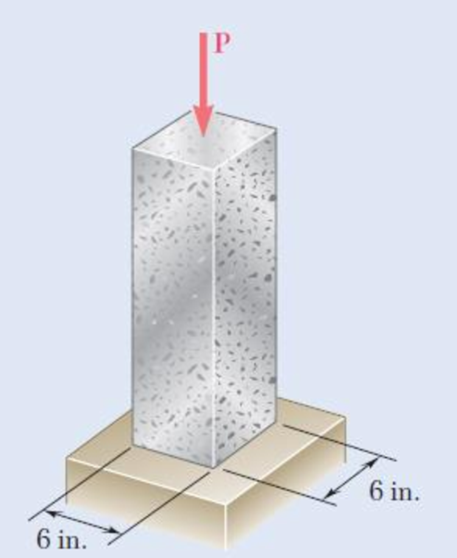
A centric load P is applied to the granite block shown. Knowing that the resulting maximum value of the shearing stress in the block is 2.5 ksi, determine (a) the magnitude of P, (b) the orientation of the surface on which the maximum shearing stress occurs, (c) the normal stress exerted on that surface, (d) the maximum value of the normal stress in the block.
Fig. P1.33 and P1.34
Expert Solution & Answer
Want to see the full answer?
Check out a sample textbook solution
Students have asked these similar questions
At a temperature of 28.75 °C a 0.4-mm gap exists between the ends of the rods shown. At a later time when the temperature has reached 123.11°C, determine the magnitude of the normal stress (in MPa) in the steel rod if L = 306.57 mm and M = 203 mm. Round off the final answer to four decimal places.
Two forces P1 and P2, with a magnitude of P1 = 15 kN and P2 = 18 kN, are applied as shown in Figure below to the end A of bar AB, which is welded to a cylindrical member BD of radius c = 20 mm. Knowing that the distance from A to the axis of member BD is a = 50 mm and assuming that all stresses remain below the proportional limit of the material, determine the normal and shearing stresses at points H and K of the transverse section of member BD located at a distance b = 60 mm from end B,
In many situations it is known that the normal stress in a given direc-tion is zero. For example, σz= 0 in the case of the thin plate shown. For this case, which is known as plane stress, show that if the strains εx and εy have been determined experimentally, we can express σx, σyand εz as follows:
Chapter 1 Solutions
Mechanics of Materials - With Access
Ch. 1.2 - Two solid cylindrical rods AB and BC are welded...Ch. 1.2 - Two solid cylindrical rods AB and BC are welded...Ch. 1.2 - Two solid cylindrical rods AB and BC are welded...Ch. 1.2 - Two solid cylindrical rods AB and BC are welded...Ch. 1.2 - A strain gage located at C on the surface of bone...Ch. 1.2 - Two brass rods AB and BC, each of uniform...Ch. 1.2 - Each of the four vertical links has an 8 36-mm...Ch. 1.2 - Link AC has a uniform rectangular cross section 18...Ch. 1.2 - Three forces, each of magnitude P = 4 kN, are...Ch. 1.2 - Link BD consists of a single bar 1 in. wide and 12...
Ch. 1.2 - For the Pratt bridge truss and loading shown,...Ch. 1.2 - The frame shown consists of four wooden members,...Ch. 1.2 - An aircraft tow bar is positioned by means of a...Ch. 1.2 - Two hydraulic cylinders are used to control the...Ch. 1.2 - Determine the diameter of the largest circular...Ch. 1.2 - Two wooden planks, each 12 in. thick and 9 in....Ch. 1.2 - When the force P reached 1600 lb, the wooden...Ch. 1.2 - A load P is applied to a steel rod supported as...Ch. 1.2 - The axial force in the column supporting the...Ch. 1.2 - Three wooden planks are fastened together by a...Ch. 1.2 - A 40-kN axial load is applied to a short wooden...Ch. 1.2 - An axial load P is supported by a short W8 40...Ch. 1.2 - Link AB, of width b = 2 in. and thickness t=14...Ch. 1.2 - Determine the largest load P that can be applied...Ch. 1.2 - Knowing that = 40 and P = 9 kN, determine (a) the...Ch. 1.2 - The hydraulic cylinder CF, which partially...Ch. 1.2 - For the assembly and loading of Prob. 1.7,...Ch. 1.2 - Two identical linkage-and-hydraulic-cylinder...Ch. 1.5 - Two wooden members of uniform rectangular cross...Ch. 1.5 - Two wooden members of uniform rectangular cross...Ch. 1.5 - The 1.4-kip load P is supported by two wooden...Ch. 1.5 - Two wooden members of uniform cross section are...Ch. 1.5 - A centric load P is applied to the granite block...Ch. 1.5 - A 240-kip load P is applied to the granite block...Ch. 1.5 - A steel pipe of 400-mm outer diameter is...Ch. 1.5 - A steel pipe of 400-mm outer diameter is...Ch. 1.5 - A steel loop ABCD of length 5 ft and of 38-in....Ch. 1.5 - Link BC is 6 mm thick, has a width w = 25 mm, and...Ch. 1.5 - Link BC is 6 mm thick and is made of a steel with...Ch. 1.5 - Members AB and BC of the truss shown are made of...Ch. 1.5 - Members AB and BC of the truss shown are made of...Ch. 1.5 - Link AB is to be made of a steel for which the...Ch. 1.5 - Two wooden members are joined by plywood splice...Ch. 1.5 - For the joint and loading of Prob. 1.43, determine...Ch. 1.5 - Three 34-in.-diameter steel bolts are to be used...Ch. 1.5 - Three steel bolts are to be used to attach the...Ch. 1.5 - A load P is supported as shown by a steel pin that...Ch. 1.5 - A load P is supported as shown by a steel pin that...Ch. 1.5 - A steel plate 14 in. thick is embedded in a...Ch. 1.5 - Determine the factor of safety for the cable...Ch. 1.5 - Link AC is made of a steel with a 65-ksi ultimate...Ch. 1.5 - Solve Prob. 1.51, assuming that the structure has...Ch. 1.5 - Each of the two vertical links CF connecting the...Ch. 1.5 - Solve Prob. 1.53, assuming that the pins at C and...Ch. 1.5 - In the structure shown, an 8-mm-diameter pin is...Ch. 1.5 - In an alternative design for the structure of...Ch. 1.5 - Prob. 57PCh. 1.5 - The Load and Resistance Factor Design method is to...Ch. 1 - In the marine crane shown, link CD is known to...Ch. 1 - Two horizontal 5-kip forces are applied to pin B...Ch. 1 - For the assembly and loading of Prob. 1.60,...Ch. 1 - Two steel plates are to be held together by means...Ch. 1 - A couple M of magnitude 1500 N m is applied to...Ch. 1 - Knowing that link DE is 18 in. thick and 1 in....Ch. 1 - A 58-in.-diameter steel rod AB is fitted to a...Ch. 1 - In the steel structure shown, a 6-mm-diameter pin...Ch. 1 - Prob. 67RPCh. 1 - A force P is applied as shown to a steel...Ch. 1 - The two portions of member AB are glued together...Ch. 1 - The two portions of member AB are glued together...
Knowledge Booster


Learn more about
Need a deep-dive on the concept behind this application? Look no further. Learn more about this topic, mechanical-engineering and related others by exploring similar questions and additional content below.Similar questions
- Two steel plates are to be held together by means of 16-mm-diameter high-strength steel bolts fitting snugly inside cylindrical brass spacers. Knowing that the average normal stress must not exceed 205 MPa in the bolts and 132 MPa in the spacers, determine the outer diameter of the spacers that yields the most economical and safe design. The outer diameter of the spacers that yields the most economical and safe design is mm.arrow_forwardPART 2: Determine the shear force acting at each of the following locations: (a) x = 0+ ft (i.e., just to the right of support A) (b) x = 14.0 ft (i,e., at point B.) (c) x = 20.5- ft (i.e., just to the left of the support C) (d) x = 20.5+ ft (i.e., just to the right of the support (C) (e)x=27.5ft Note that x = 0 at support A. When entering your answers, use the shear-force sign convention detailed in Section 7.2. My Answers: Correct (a) V= 105.823 kips (b)V= -48.177 kips (c) V= -119.677 kips (d)V= 88 kips (e) V= 10.9998 kips PART 3: Determine the bending moment acting at each of the following locations: (a) x = 14.0- ft (i.e., just to the left of point B.) (b) x = 14.0+ ft(i.e., just to the right of point B.) (c) x = 20.5 ft (i.e. at point C) (d)x=27.5ft Note that x = 0 at support A. When entering your answers, use the shear-force sign convention detailed in Section 7.2. My Answers: Correct (a) M = 403.522 kips-ft (b) M = 193.522 kips-ft (c) M = -352.0035 kips-ft (d) M =…arrow_forwardA seamless cylinder of storage capacity of 0.03m3 is subjected to an internal pressure of 21 MPa. The allowable stress in the material of cylinder is 350N/mm².Determine the length of the cylinder if it is twice the diameter of the cylinder.8mm A seamless cylinder of storage capacity of 0.03mᵌis subjected to an internal pressure of 21MPa. The ultimate strength of material of cylinder is 350N/mm².Determine the length of the cylinder if it is twice the diameter of the cylinder.540mmarrow_forward
- Two wooden planks, each 1212 in. thick and 9 in. wide, are joined by the dry mortise joint shown. Knowing that the wood used shears off along its grain when the average shearing stress reaches 1.8 ksi, determine the magnitude P of the axial load that will cause the joint to fail. The magnitude P of the axial load that will cause the joint to fail is kips.arrow_forwardA rectangular steel block is 4 inches long in the x direction, 2 inches long in the y direction, and 3 inches long in the z direction. The block is subjected to a triaxial loading of three resultant forces as follows: 72 kips compression in the x direction, 60 kips tension in the y direction, and 56 kips tension in the z direction. If ν = 1/3 and E = 29 x 106 psi, ( a ) determine the single resultant load in the z direction that would produce the same deformation in x direction as the original loadings. ( b ) determine the single resultant load in the y direction that would produce the same deformation in x direction as the original loadings.arrow_forwarda. Determine the normal stress in the element GF if the area is 10 in2, knowing that the load W is 1500lb, express your answer in psi b. determine the normal stress in the element EC if the area is 20 in2arrow_forward
- A 5.3-m-long steel rod must not stretch more than 2.71 mm and the normal stress must not exceed 181 MPa when the rod is subjected to a 9.99-kNaxial load. Knowing that E = 199.3 GPa, determine the required radius of the rod in mm. Express your answer in four decimal places.arrow_forwardProblem 1 A centric load P is applied to the granite block shown below. Knowing theresulting maximum value of the shearing stress in the block is 2.5 ksi, determine:The magnitude of PThe normal stress exerted on the surface where the shearing stress is the maximum valueThe maximum value of normal stressDraw an FBD showing the surface of maximum shearing stress, the maximum shearingstress and the normal stress occurring in that surface.arrow_forwardThe stress produced by a suddenly applied load as compared to that produced by the same load when applied gradually is: A. 1.5 times B. 2 times C. 3 times D. 4 timesarrow_forward
- 6. A strain gage located at C on the surface of bone AB indicates that the average normal stress in the bone is 3.80 MPa when the bone is subjected to two 1200-N forces as shown. Assuming the cross section of the bone at C to be annular and knowing that its outer diameter is 25 mm, determine the inner diameter of the bone’s cross section at C.arrow_forwardFor the truss and loading shown, determine the magnitude of the normal stress(in psi) in member CE, knowing that the cross-sectional area of that member is 3.67 in2 if P = 30505 lb, Q = 34758 lb, and y = 7.35 ft. Round off the final answer to two decimal places.arrow_forwardFrom the given bracket shown, which consist of two plates riveted to the column by 4-22mm Ø rivets which is subjected to an eccentric load of 150 kN. 1. Which of the following gives the shearing stress due to axial load only? a. 49.325 MPa b. 70.25 MPa c. 80.47 MPa d. 68.25 MPa 2.. Which of the following gives the shearing stress due to moment alone? a. 69.76 MPa b. 70.94 MPa c. 56.39 MPa d. 64.32 MPa 3. Which of the following gives the maximum shearing stress? a. 110.30 MPa b. 120.40 MPa c. 140.50 MPa d. 105.70 MPaarrow_forward
arrow_back_ios
SEE MORE QUESTIONS
arrow_forward_ios
Recommended textbooks for you
 Elements Of ElectromagneticsMechanical EngineeringISBN:9780190698614Author:Sadiku, Matthew N. O.Publisher:Oxford University Press
 Mechanics of Materials (10th Edition)Mechanical EngineeringISBN:9780134319650Author:Russell C. HibbelerPublisher:PEARSON
 Thermodynamics: An Engineering ApproachMechanical EngineeringISBN:9781259822674Author:Yunus A. Cengel Dr., Michael A. BolesPublisher:McGraw-Hill Education
 Control Systems EngineeringMechanical EngineeringISBN:9781118170519Author:Norman S. NisePublisher:WILEY
 Mechanics of Materials (MindTap Course List)Mechanical EngineeringISBN:9781337093347Author:Barry J. Goodno, James M. GerePublisher:Cengage Learning
 Engineering Mechanics: StaticsMechanical EngineeringISBN:9781118807330Author:James L. Meriam, L. G. Kraige, J. N. BoltonPublisher:WILEY
Elements Of Electromagnetics
Mechanical Engineering
ISBN:9780190698614
Author:Sadiku, Matthew N. O.
Publisher:Oxford University Press
Mechanics of Materials (10th Edition)
Mechanical Engineering
ISBN:9780134319650
Author:Russell C. Hibbeler
Publisher:PEARSON
Thermodynamics: An Engineering Approach
Mechanical Engineering
ISBN:9781259822674
Author:Yunus A. Cengel Dr., Michael A. Boles
Publisher:McGraw-Hill Education
Control Systems Engineering
Mechanical Engineering
ISBN:9781118170519
Author:Norman S. Nise
Publisher:WILEY
Mechanics of Materials (MindTap Course List)
Mechanical Engineering
ISBN:9781337093347
Author:Barry J. Goodno, James M. Gere
Publisher:Cengage Learning
Engineering Mechanics: Statics
Mechanical Engineering
ISBN:9781118807330
Author:James L. Meriam, L. G. Kraige, J. N. Bolton
Publisher:WILEY
Strain energy and strain energy density introduced; Author: Engineer4Free;https://www.youtube.com/watch?v=m14sqLGg4BQ;License: Standard youtube license