
Videos
Solve Prob. 1.51, assuming that the structure has been redesigned to use
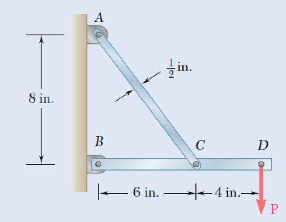
1.51 Link AC is made of a steel with a 65-ksi ultimate normal stress and has a
Fig. P1.51

Trending nowThis is a popular solution!

Chapter 1 Solutions
MECHANICS OF MATERIALSW/CONNECT>(LL)<>


- Determine the largest axial load P that can be safely supported by a flat steel bar consisting of two portions, both 10 mm thick and, respectively, 40 and 80 mm wide, connected by fillets of radius r=4 mm. Assume an allowable normal stress of 180 MPa.arrow_forwardIn the steel structure shown, a 6-mm-diameter pin is used at C and 12-mm-diameter pins are used at B and D. The ultimate shearing stress is 150 MPa at all connections, and the ultimate normal stress is 350 MPa in link BD. Knowing that a factor of safety of 3.0 is desired, determine the largest load P that can be applied at A. Note that link BD is not reinforced around the pin holes. The largest load P that can be applied at A is kN.arrow_forwardThe frame shown consists of four wooden members, ABC, DEF, BE,and CF. Knowing that each member has a 2x 4-in. rectangular cross section and that each pin has a 1/2-in. diameter, determine the maximum value of the average normal stress (a) in member BE, (b) in member CF.arrow_forward
- In the structure shown, an 8-mm diameter pin is used at A, and 12-mm diameter pins are used at B and D. Knowing that the ultimate shearing stress is 100 MPa at all connections and that the ultimate normal stress is 250 MPa in each of the two links joining B and D, determine the allowable load P if an overall factor ofsafety of 3.0 is desired.arrow_forwardIn the structure shown, an 8-mm-diameter pin is used at A, and 12-mm-diameter pins are used at B and D. Knowing that the ultimate shearing stress is 100 MPa at all connections and that the ultimate normal stress is 250 MPa in each of the two links joining B and D, determine the allowable load P if an overall factor of safety of 2.6 is desired.arrow_forwardAn offset h must be introduced into a metal tube of 0.75-in. outer diameter and 0.08-in. wall thickness. Knowing that the maximum stress after the offset is introduced must not exceed 4 times the stress in the tube when it was straight, determine the largest offset that can be used.arrow_forward
- Each of the four vertical Ilinks has an 8 x 36-mm uniform rectangular cross section and each of the four pins has a 16-mm diameter. Take P= 19 kN. 0.4 m C 0.25 m 0.2 m B. P Determine the average bearing stress at Bin member ABC, knowing that this member has a 10 x 50-mm uniform rectangular cross section. MPa. The average bearing stress at Bin member ABC is.arrow_forwardTwo wooden members of 80 *120-mm uniform rectangular cross section are joined by the simple glued scarf splice shown. Knowing that β=22° and that the maximum allowable stresses in the joint are, respectively, 400 kPa in tension (perpendicular to the splice) and 600 kPa in shear (parallel to the splice), determine the largest centric load P that can be appliedarrow_forwardA 20 mm diameter rod BC has flat ends of 20 mm x 40 mm rectangular cross section, while the boom AB has a 30 x 50 mm rectangular cross section and is fitted with a clevis at the end B. Both members are connected at B by a pin from which the 30 kN load is suspended by means of a U-Shaped bracket. Boom AB is supported at A by a pin fitted into a double bracket, while rod BC is connected at C to a single bracket. All pins are 25 mm diameter. Determine the normal stresses in members AB and BC; shearing stresses and bearing stresses at A, B and C.arrow_forward
- Straight rods of 0.30-in. diameter and 200-ft length are sometimes used to clear underground conduits of obstructions or to thread wires through a new conduit. The rods are made of high-strength steel and, for storage and transportation, are wrapped on spools of 5-ft diameter. Assuming that the yield strength is not exceeded, determine (a) the maximum stress in a rod, when the rod, which was initially straight, is wrapped on the spool, (b) the corresponding bending moment in the rod. Use E= 29 * 106 psi.arrow_forwardIn the structure shown, an 8-mm-diameter pin is used at A and 12 mmdiameter pins are used at B and D. Knowing that the ultimate shearingstress is 100 MPa at all connections and the ultimate normal stress is 250 MPa in each of the two links joining B and D, determine the allowable load P if an overall factor of safety of 3.0 is desired.arrow_forwardThe steel tie bar shown is to be designed to carry a tension force of magnitudeP=120 kN when bolted between double brackets at A and B. The bar will be fabricated from 20-mm-thick plate stock. For the grade of steel tobe used, the maximum allowable stresses are σ =175 MPa, τ =100 MPa,and σb=350 MPa. Design the tie bar by determining the required values of(a) the diameter d of the bolt, (b) the dimension b at each end of the bar, and(c) the dimension h of the bar.arrow_forward
 Elements Of ElectromagneticsMechanical EngineeringISBN:9780190698614Author:Sadiku, Matthew N. O.Publisher:Oxford University Press
 Mechanics of Materials (10th Edition)Mechanical EngineeringISBN:9780134319650Author:Russell C. HibbelerPublisher:PEARSON
 Thermodynamics: An Engineering ApproachMechanical EngineeringISBN:9781259822674Author:Yunus A. Cengel Dr., Michael A. BolesPublisher:McGraw-Hill Education
 Control Systems EngineeringMechanical EngineeringISBN:9781118170519Author:Norman S. NisePublisher:WILEY
 Mechanics of Materials (MindTap Course List)Mechanical EngineeringISBN:9781337093347Author:Barry J. Goodno, James M. GerePublisher:Cengage Learning
 Engineering Mechanics: StaticsMechanical EngineeringISBN:9781118807330Author:James L. Meriam, L. G. Kraige, J. N. BoltonPublisher:WILEY