SHIGLEY'S MECH.ENGR...(LL)-PKG.>CUSTOM<
10th Edition
ISBN: 9781260028379
Author: BUDYNAS
Publisher: MCG/CREATE
expand_more
expand_more
format_list_bulleted
Concept explainers
Videos
Textbook Question
Chapter 16, Problem 13P
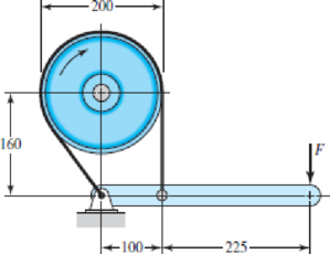
The brake shown in the figure has a coefficient of friction of 0.30 and is to operate using a maximum force F of 400 N. If the band width is 50 mm, find the maximum band tensions and the braking torque.
Problem 16–13
Dimensions in millimeters.
Expert Solution & Answer
Want to see the full answer?
Check out a sample textbook solution
Students have asked these similar questions
For the drum brake shown in the following figure, there is an inner rim diameter of 280 mm and dimension a = 90 mm. The shoes have a face width of 30 mm. The force exerted by the cylinder hydraulic is 1000 N and the average coefficient of friction is 0.3.
Determine:
a) The maximum pressure in each shoe;
b) The braking torque;
c) Reactions resulting from the pivot pin;
The two square-jaw grips have the dimensions shown in the figure and are made of mild steel. The clutch is designed to transmit a power of 1.8 kW at 600 rpm. Calculate the surface pressure and shear stresses on the wedges and jaws. they all in mm
The width of the simple band brake shown in the figure is 30 mm. The coefficient of friction between the brake and the drum surface is 0.20. Determine the braking torque and thickness of the band if the tensile stress is not to exceed 65 N/mm2.
Chapter 16 Solutions
SHIGLEY'S MECH.ENGR...(LL)-PKG.>CUSTOM<
Ch. 16 - The figure shows an internal rim-type brake having...Ch. 16 - For the brake in Prob. 16-1, consider the pin and...Ch. 16 - In the Figure for Prob. 16-1, the inside rim...Ch. 16 - The figure shows a 400-mm-diameter brake drum with...Ch. 16 - The block-type hand brake shown in the figure has...Ch. 16 - Suppose the standard deviation of the coefficient...Ch. 16 - The brake shown in the figure has a coefficient of...Ch. 16 - Prob. 8PCh. 16 - Prob. 9PCh. 16 - Prob. 10P
Ch. 16 - The maximum band interface pressure on the brake...Ch. 16 - The drum for the band brake in Prob. 1611 is 12 in...Ch. 16 - The brake shown in the figure has a coefficient of...Ch. 16 - The figure depicts a band brake whose drum rotates...Ch. 16 - The figure shows a band brake designed to prevent...Ch. 16 - A plate clutch has a single pair of mating...Ch. 16 - A hydraulically operated multidisk plate clutch...Ch. 16 - Prob. 18PCh. 16 - A cone clutch has D = 12 in, d = 11 in, a cone...Ch. 16 - Prob. 20PCh. 16 - A two-jaw clutch has the dimensions shown in the...Ch. 16 - Prob. 22PCh. 16 - Prob. 23PCh. 16 - Prob. 24PCh. 16 - Using the data of Table 16-6, find the mean output...Ch. 16 - When a motor armature inertia, a pinion inertia,...Ch. 16 - For the conditions of Prob. 1627, make a plot of...Ch. 16 - Prob. 29PCh. 16 - Prob. 30PCh. 16 - Prob. 31P
Knowledge Booster


Learn more about
Need a deep-dive on the concept behind this application? Look no further. Learn more about this topic, mechanical-engineering and related others by exploring similar questions and additional content below.Similar questions
- The block-type parking brake shown in the figure has a width of 49 mm and an average friction coefficient of 0.32. Calculate the maximum pressure and braking moment on the shoe to provide a thrust of 419 N in the anti-clockwise system?arrow_forward6. Design a clamp coupling for transmitting 36 kW, at 200 rpm. Allowable shear stress in shaft is 45 MPa, allowable shear stress in key is 40 MPa, and allowable crushing stress in key is 90 MPa. The number of bolts joining the two halves is 4. The permissible tensile stress in bolts is 60 MPa. The coefficient of friction between the muff and shaft can be taken as 0.25arrow_forwardTwo pulleys, one 650 mm diameter and the other 400 mm diameter, on parallel shafts 1.5 m apart are connected by a flat belt. Find the length of the belt required and the angle of contact between the belt and each pulley. What power can be transmitted by the belt when the larger pulley rotates at 1200 rev/min, if the maximum permissible tension in the belt is 10 kN, and the coefficient of friction between the belt and pulley is 0.05? give proper explaination and dont give handwritten solution.arrow_forward
- The roughly position of the automobile jack shown in the figure is a square screw with a single blade at both ends. ABC is controlled by a bolt (right-hand threaded in A, left-handed in C). square of the bolt screw has a pitch of 2.5 mm and an average diameter of 9 mm. between the bolt and the jack limbs The coefficient of static friction is 0.15, taking into account the position and load shown, you can use the jack Find the magnitude of the torque that must be applied to raise it.arrow_forwardA differential band brake is shown in the figure. The diameter of the drum is 800 mm. The coefficient of friction between the band and the drum is 0.3 and the angle of embrace is 240°. When a force of 777 N is applied at the free end of the lever, find: a. The maximum force, in Newtons, in the band for the clockwise rotation of the drum b. The minimum force, in Newtons, in the band for the clockwise rotation of the drum c. The maximum force, in Newtons, in the band for the counter clockwise rotation of the drum d. The minimum force, in Newtons, in the band for the counter clockwise rotation of the drum e. The torque which can be applied by the brake, in N-m, for the clockwise rotation of the drum.arrow_forwardIn a particular application, the radial load acting on a ball bearing is 5 kN and the expected life for 90% of the hearings is 8000 Calculate the dynamic load carrying capacity of the bearing, when the shaft rotates at 1450 rpm.arrow_forward
- 8. Design a clamp coupling for transmitting 25 kW at 300 rpm. Allowable shear stresses in shaft and key are 50 MPa and 45 MPa, respectively. The number of bolts joining the two halves of muff is 4. The permissible tensile stress in the bolt is 70 MPa and the permissible crushing stress in the key is 90 MPa. The coeffi cient of friction between the muff of the CI and the shaft of steel is 0.20.arrow_forwardThe following figure shows a belt brake system operating on a brake drum of the hoisting mechanism. It consists of a cylinder with a diameter of 325 mm, the end of which is the elastic belt connected to both ends of the elastic belt by a crank arm articulated at B and the angle of rotation = 225 degrees. And the coefficient of friction is 0.3 and the latching force is f. Find the necessary F to generate a torque of 350 on the cylinder while it is rotating in the direction shown? Note that s = c = 135mm a = 500mm. 35mmarrow_forwardFor the same question, the Impeller hub will be pressed onto the taper shaft with the Nut. How much FORCE should the nut create for this? Also, if the nut loosens and falls off, calculate whether the connection will be DISCONNECTED by itself. (Do not take the values from the previous question, use the values given in this question!) Engine power P=27 kW, RPM n=1684 rpm, Connection MEDIUM vibrating, Conical inclination angle α=1, Coefficient of Friction μ=0.3 , Average of the conical part diameter d=24 mm, connection width b=96 mmarrow_forward
- The pedal system shown in the figure is exerted by both an up and down mechanism. These forces are Fmax=350*SN/10 N, Fmin=-150*SN/10 N. It is desired that h/b = 5 seen in the figure. This piece is AISI 1040 and has a maximum tensile stress of 670Mpa and a yield stress of 540Mpa. Known weakening factors are known as kb=ky=kd=0.8. The notch factor for all stresses is assumed to be Kç=1.5. It is desired to last up to its minimum indefinite life at the cross-section measurement point (bxh) shown in the figure. According to Goodman theory, what should be the minimum size (b and h value) of this section in order to meet this condition. SN=89arrow_forwardQ 3. The brake shown in the figure uses a band that has a coefficient of friction equivalent to rigid molded asbestos (dry) and is to operate using a maximum force F of 400 N. If the band width is 50 mm, find the band tensions and the braking torque.arrow_forwardThe worm shaft shown in the figure transmits 1-kW at 500 rev/min. A static forceanalysis results are also shown in the figure. Bearing A is to be an angular-contact ballbearing mounted to take the 2.75 kN thrust load. The bearing at B is to take only theradial load, so a straight roller bearing will be employed. Use an application factor of1.2, a desired life of 25 kh, and a combined reliability goal of 0.99. (a)Specify each bearing by giving all required charecteristics. (b) Determine the radial and thrust components of loads on each bearing. (c) Make a design assessment for each bearing and of the system.arrow_forward
arrow_back_ios
SEE MORE QUESTIONS
arrow_forward_ios
Recommended textbooks for you
 Elements Of ElectromagneticsMechanical EngineeringISBN:9780190698614Author:Sadiku, Matthew N. O.Publisher:Oxford University Press
 Mechanics of Materials (10th Edition)Mechanical EngineeringISBN:9780134319650Author:Russell C. HibbelerPublisher:PEARSON
 Thermodynamics: An Engineering ApproachMechanical EngineeringISBN:9781259822674Author:Yunus A. Cengel Dr., Michael A. BolesPublisher:McGraw-Hill Education
 Control Systems EngineeringMechanical EngineeringISBN:9781118170519Author:Norman S. NisePublisher:WILEY
 Mechanics of Materials (MindTap Course List)Mechanical EngineeringISBN:9781337093347Author:Barry J. Goodno, James M. GerePublisher:Cengage Learning
 Engineering Mechanics: StaticsMechanical EngineeringISBN:9781118807330Author:James L. Meriam, L. G. Kraige, J. N. BoltonPublisher:WILEY
Elements Of Electromagnetics
Mechanical Engineering
ISBN:9780190698614
Author:Sadiku, Matthew N. O.
Publisher:Oxford University Press
Mechanics of Materials (10th Edition)
Mechanical Engineering
ISBN:9780134319650
Author:Russell C. Hibbeler
Publisher:PEARSON
Thermodynamics: An Engineering Approach
Mechanical Engineering
ISBN:9781259822674
Author:Yunus A. Cengel Dr., Michael A. Boles
Publisher:McGraw-Hill Education
Control Systems Engineering
Mechanical Engineering
ISBN:9781118170519
Author:Norman S. Nise
Publisher:WILEY
Mechanics of Materials (MindTap Course List)
Mechanical Engineering
ISBN:9781337093347
Author:Barry J. Goodno, James M. Gere
Publisher:Cengage Learning
Engineering Mechanics: Statics
Mechanical Engineering
ISBN:9781118807330
Author:James L. Meriam, L. G. Kraige, J. N. Bolton
Publisher:WILEY
Mechanical Design (Machine Design) Clutches, Brakes and Flywheels Intro (S20 ME470 Class 15); Author: Professor Ted Diehl;https://www.youtube.com/watch?v=eMvbePrsT34;License: Standard Youtube License