
Videos
Figure P16.55 is a classic CMOS logic gate. (a) What is the logic function performed by the circuit? (b) Design the NMOS network. (c) Determine the transistor W/L ratios to provide symmetrical switching times equal to the basic CMOS inverter with
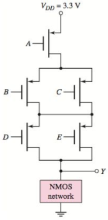
Figure P16.55
Want to see the full answer?
Check out a sample textbook solution
Chapter 16 Solutions
MICROELECT. CIRCUIT ANALYSIS&DESIGN (LL)


- Implement logic function shown below with static CMOS gate. Out = ABC + ĀB + BC + ACarrow_forwardBriefly describe the internal and external control of inverters.arrow_forwardUsing the sine PWM method with the full bridge inverter below, it is desired to generate a voltage of 50 Hz on the serial RL load. A voltage of 120 V DC is applied to the input of the inverter circuit. Amplitude modulation rate ma -0.9 and frequency modulation rate mf -19. The resistance of the series RL load is 15 OHM and the coil inductance is 40 mH. a) What is the power drawn by the load resistor?b) What is the total harmonic distortion value (THD) of the load current?arrow_forward
- Describe the functionality of a three-state inverter.arrow_forwardDesign an asymmetrical inverter to meet the delay specificationa symmetrical CMOS reference inverter to provide a delay of 1 ns when driving a 10-pF load.(a) Assume VDD =2.5 V. (b) Assume VDD =1.8 V and VT N =−VT P =0.45 V. with (W/L)P = 2(W/L)N .arrow_forward(e) Describe, with the help of sketches, the definition and meaning of noise margins in an inverter logic gate.arrow_forward
- Discussion and calculations 1. What is the function of inverter? 2. What are the differences between half-bridge and full-bridge inverters ? 3. Compare between the simulation and theoretical results for output voltages.arrow_forwardAssume Vth = 1V and k = 50mA/V2. Given the schematic below, do the following: 1) Indicate and verify the state of each MOSFET and ?0 for the following input combinations. Fill-out the table below for each assumed state of the MOSFET for every input combination. Use ?ds,on approximation for linear operation. 2) Determine what kind of logic circuit is implemented in the circuit.arrow_forwardA square-wave inverter has an R-L load with R = 15 N and L = 10 mH. The inverter output frequency is 400 Hz 1. Determine the value of the de source required to establish a load current which has a fundamental frequency component of 10 A rms. (b) Determine the THD of the load current. (c) Sketch the output and input currents. (a)arrow_forward
- Q5 Consider a four-input CMOS NAND logic gate. Draw the circuit, then: Q6 a) Determine the W/L ratios of the transistors to provide for symmetrical switching based blcon the CMOS inverter design with (W/L) 2 and (W/L), 4. b) If the load capacitance of the NOR gate becomes 5 times the original value, determine the required W/L ratios to provide the same switching speed as the logic gate in part (a). Design a CMOS circuit to implement the logic function. The design should not include a CMOS inverter at the output. F= ABC + ACD + ACDarrow_forwardMay I know the clear explanation about this problem? What methods are used to control the frequency and output voltage of an inverter? What is the purpose of the base-drive resistors, R2 and R3, in the circuit below?arrow_forwardWhat will be the fundamental frequency for the following circuit if each inverter delay is 100 nsec? Outputarrow_forward
 Introductory Circuit Analysis (13th Edition)Electrical EngineeringISBN:9780133923605Author:Robert L. BoylestadPublisher:PEARSON
 Delmar's Standard Textbook Of ElectricityElectrical EngineeringISBN:9781337900348Author:Stephen L. HermanPublisher:Cengage Learning
 Programmable Logic ControllersElectrical EngineeringISBN:9780073373843Author:Frank D. PetruzellaPublisher:McGraw-Hill Education
 Fundamentals of Electric CircuitsElectrical EngineeringISBN:9780078028229Author:Charles K Alexander, Matthew SadikuPublisher:McGraw-Hill Education
 Electric Circuits. (11th Edition)Electrical EngineeringISBN:9780134746968Author:James W. Nilsson, Susan RiedelPublisher:PEARSON
 Engineering ElectromagneticsElectrical EngineeringISBN:9780078028151Author:Hayt, William H. (william Hart), Jr, BUCK, John A.Publisher:Mcgraw-hill Education,