
Statics and Mechanics of Materials Plus Mastering Engineering with Pearson eText - Access Card Package (5th Edition)
5th Edition
ISBN: 9780134301006
Author: Russell C. Hibbeler
Publisher: PEARSON
expand_more
expand_more
format_list_bulleted
Concept explainers
Videos
Textbook Question
Chapter 16.2, Problem 3P
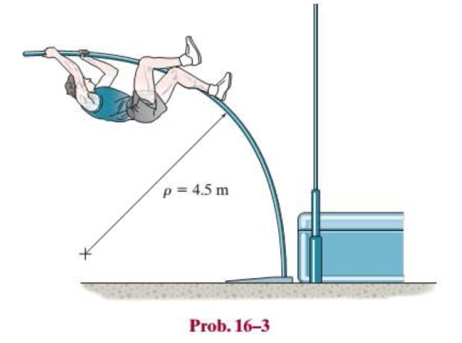
A picture is taken of a man performing a pole vault, and the minimum radius of curvature of the pole is estimated by measurement to be 4.5 m. If the pole is 40 mm in diameter and it is made of a glass-reinforced plastic for which Eg = 131 GPa, determine the maximum bending stress in the pole.
Expert Solution & Answer
Want to see the full answer?
Check out a sample textbook solution
Students have asked these similar questions
A load of 100 kN, followed by another load of 50 kN, at a distance of 10 metres, advances across a girder with a 100-metre span. Obtain an expression for the maximum bending moment at a section of the girder at a distance of z metres from an abutment. Please provide solutions.
Answer is z(140-1.5z) for z< (100/3)m;(100-z)(1.5z-5) for z>(100/3) m.
The structure shown below consists of a brass core inserted into a steel tube of cross section square. If a moment of 8 kN × m is applied at its end, determine the maximum bending stress in the bar. Elaton = 100 GPa, Steel = 200 GPa.
Wooden beams and steel plates are securely bolted together to form the composite member shown. Using the data given below, determine the largest permissible bending moment when the compos-ite member is bent about a horizontal axis.Modulus of elasticity 2 * 106 psi 29 * 106 psi Allowable stress 2000 psi 22 ksi
Chapter 16 Solutions
Statics and Mechanics of Materials Plus Mastering Engineering with Pearson eText - Access Card Package (5th Edition)
Ch. 16.2 - In each ease, determine the internal bending...Ch. 16.2 - Prob. 1FPCh. 16.2 - Determine the slope and deflection of end A of the...Ch. 16.2 - Prob. 3FPCh. 16.2 - Prob. 4FPCh. 16.2 - Determine the maximum deflection of the simply...Ch. 16.2 - Prob. 6FPCh. 16.2 - An L2 steel strap having a thickness of 0.125 in....Ch. 16.2 - The L2 steel blade of the band saw wraps around...Ch. 16.2 - A picture is taken of a man performing a pole...
Ch. 16.2 - Determine the equation of the elastic curve for...Ch. 16.2 - Determine the deflection of end C of the...Ch. 16.2 - Prob. 6PCh. 16.2 - The A-36 steel beam has a depth of 10 in. and is...Ch. 16.2 - Prob. 8PCh. 16.2 - Determine the equations of the elastic curve for...Ch. 16.2 - Determine the equations of the elastic curve using...Ch. 16.2 - Determine the equations of the elastic curve using...Ch. 16.2 - Prob. 12PCh. 16.2 - Determine the maximum deflection of the beam and...Ch. 16.2 - The simply supported shaft has a moment of inertia...Ch. 16.2 - A torque wrench is used to tighten the nut on a...Ch. 16.2 - The pipe can be assumed roller supported at its...Ch. 16.2 - Determine the equations of the elastic curve for...Ch. 16.2 - The bar is supported by a roller constraint at B,...Ch. 16.2 - The bar is supported by a roller constraint at B,...Ch. 16.2 - Determine the equations of the elastic curve using...Ch. 16.2 - Prob. 21PCh. 16.2 - Determine the elastic curve for the cantilevered...Ch. 16.2 - Prob. 23PCh. 16.2 - Prob. 24PCh. 16.2 - The floor beam of the airplane is subjected to the...Ch. 16.2 - Determine the maximum deflection of the simply...Ch. 16.2 - The beam is made of a material having a specific...Ch. 16.2 - Determine the slope at end B and the maximum...Ch. 16.2 - Prob. 29PCh. 16.2 - Determine the equations of the elastic curve using...Ch. 16.3 - The shaft is supported at A by a journal bearing...Ch. 16.3 - The shaft supports the two pulley loads shown....Ch. 16.3 - Prob. 33PCh. 16.3 - Prob. 34PCh. 16.3 - The beam is subjected to the load shown. Determine...Ch. 16.3 - Prob. 36PCh. 16.3 - Determine the equation of the elastic curve and...Ch. 16.3 - Prob. 38PCh. 16.3 - Prob. 39PCh. 16.3 - Determine the slope at A and the deflection of end...Ch. 16.3 - Determine the maximum deflection in region AB of...Ch. 16.3 - Prob. 42PCh. 16.3 - Prob. 43PCh. 16.3 - Prob. 44PCh. 16.4 - The W10 15 cantilevered beam is made of A-36...Ch. 16.4 - The W10 15 cantilevered beam is made of A-36...Ch. 16.4 - The W14 43 simply supported beam is made of A992...Ch. 16.4 - The W14 43 simply supported beam is made of A992...Ch. 16.4 - The W14 43 simply supported beam is made of A-36...Ch. 16.4 - The W14 43 simply supported beam is made of A-36...Ch. 16.4 - The W8 48 cantilevered beam is made of A-36 steel...Ch. 16.4 - The beam supports the loading shown. Code...Ch. 16.4 - Prob. 53PCh. 16.4 - The W8 48 cantilevered beam is made of A-36 steel...Ch. 16.4 - Prob. 55PCh. 16.4 - Prob. 56PCh. 16.4 - Prob. 57PCh. 16.4 - The assembly consists of a cantilevered beam CB...Ch. 16.4 - Prob. 59PCh. 16.4 - Prob. 60PCh. 16.5 - Determine the reactions at the fixed support A and...Ch. 16.5 - Prob. 8FPCh. 16.5 - Determine the reactions at the fixed support A and...Ch. 16.5 - Prob. 10FPCh. 16.5 - Prob. 11FPCh. 16.5 - Prob. 12FPCh. 16.5 - Prob. 61PCh. 16.5 - Determine the reactions at the supports, then draw...Ch. 16.5 - Determine the reactions at the supports, then draw...Ch. 16.5 - Prob. 64PCh. 16.5 - The beam is used to support the 20-kip load....Ch. 16.5 - Prob. 66PCh. 16.5 - Determine the reactions at the supports A and B....Ch. 16.5 - Before the uniform distributed load is applied to...Ch. 16.5 - Prob. 69PCh. 16.5 - Prob. 70PCh. 16.5 - The beam is supported by the bolted supports at...Ch. 16.5 - Prob. 72PCh. 16.5 - Prob. 73PCh. 16 - Prob. 1RPCh. 16 - Draw the bending-moment diagram for the shaft and...Ch. 16 - Prob. 3RPCh. 16 - Determine the equations of the elastic curve for...Ch. 16 - Determine the maximum deflection between the...Ch. 16 - Prob. 6RPCh. 16 - The framework consists of two A-36 steel...Ch. 16 - Prob. 8RPCh. 16 - Using the method of superposition, determine the...
Knowledge Booster


Learn more about
Need a deep-dive on the concept behind this application? Look no further. Learn more about this topic, mechanical-engineering and related others by exploring similar questions and additional content below.Similar questions
- Determine the ratios of the weights of four beams that have same length.are made of the same material,are subjected to the same lmaximum bending moment,and have the same maximum bending stress if their cross sections are (I) a rectangle with height equal to twice the width,(2) a square,(3) a circle , and (4) a pipe with outer diameter d and wall thickmess f = di% (see figures).arrow_forwardDetermine the maximum absolute values of the shear and bending moment.arrow_forwardA shaft is made of a polymer having an elliptical cross section. If it resists an internal moment of M = 50 N # m, determine the maximum bending stress in the material (a) using the flexure formula, where Iz = 1 4 p(0.08 m)(0.04 m)3, (b) using integration. Sketch a three-dimensional view of the stress distribution acting over the cross-sectional area. Here Ix = 1 4 p(0.08 m)(0.04 m)3.arrow_forward
- Determine the maximum bending stress in a cantilever beam of length 20 m. The beam is subjected to a point load at its free end and the diameter of the beam is 40 mm and elastic constant is 160 Gpa.arrow_forwardFor the beam and loads shown, draw the shear force and bending moment diagrams and determine the maximum bending stress. The beam has a cross section W = 200 x 22.5 with a section modulus value of area of 194 x 10^3 mm^3arrow_forwardThe beam is made of elastic perfectly plastic material for which sY = 345 MPa. Determine the maximum elastic moment and the plastic moment that can be applied to the cross section.arrow_forward
- The composite beam in Fig. a is made of wood and reinforced with a steel strap located on its bottom side. If the beam is subjected to a bending moment of M = 2 kN # m, determine the normal stress at points B and C. Take Ew = 12 GPa and Est = 200 GPa.arrow_forwardThe beam is constructed from four pieces of wood, glued together as shown. If M = 10 kip # ft, determine the maximum bending stress in the beam. Sketch a three-dimensional view of the stress distribution acting over the cross section.arrow_forward1. Determine the maximum positive bending moment in the beam in kN-m. 2. Determine the maximum shear in kN. 3. Determine the location of Neutral Axis, in mm, from the top of the section. 4. Determine the location of the centroid, in mm, from the left of the section. 5. Determine the moment of inertia of the section in x106 mm4 . 6. Determine the moment capacity of the section, kN-m, if fbcap≤300 MPa. 7. Determine the maximum flexural stress experienced by the beam in MPa. 8. Determine the maximum shearing stress in MPa at Neutral Axis. 9. Determine the spacing of rivets in mm. 10. Determine the maximum flexural stress at 1 m from the support at D to E in MPa.arrow_forward
- Draw the bending moment and shear diagrams for bar CD of the structure below.arrow_forwardConsider that the section is transmitting a positive bending moment about the z axis,Mz, where Mz=10 kip*in if the dimensions of the section are given in ips units, or Mz=1.13kN*m if the dimensions are in SI units. Determine the resulting stresses at the top and bottom surfaces and at every abrupt change in the cross section. Find the second moment of area, the location of the neutral axis, and the distances from the neutral axis to the top and bottom surfaces.arrow_forwardAn I section symmetrical beamhas 200mm wide flange and overall depth of 500mm. Each flange is 25mm thickand the web is 20mm thick. Determine the maximum bending moment that should be imposed in the sectionif the tensile or the compressive stressis not to exceed 40MN/m^2 and what percentage of the moment is resisted by flange or web?arrow_forward
arrow_back_ios
SEE MORE QUESTIONS
arrow_forward_ios
Recommended textbooks for you
 Elements Of ElectromagneticsMechanical EngineeringISBN:9780190698614Author:Sadiku, Matthew N. O.Publisher:Oxford University Press
 Mechanics of Materials (10th Edition)Mechanical EngineeringISBN:9780134319650Author:Russell C. HibbelerPublisher:PEARSON
 Thermodynamics: An Engineering ApproachMechanical EngineeringISBN:9781259822674Author:Yunus A. Cengel Dr., Michael A. BolesPublisher:McGraw-Hill Education
 Control Systems EngineeringMechanical EngineeringISBN:9781118170519Author:Norman S. NisePublisher:WILEY
 Mechanics of Materials (MindTap Course List)Mechanical EngineeringISBN:9781337093347Author:Barry J. Goodno, James M. GerePublisher:Cengage Learning
 Engineering Mechanics: StaticsMechanical EngineeringISBN:9781118807330Author:James L. Meriam, L. G. Kraige, J. N. BoltonPublisher:WILEY
Elements Of Electromagnetics
Mechanical Engineering
ISBN:9780190698614
Author:Sadiku, Matthew N. O.
Publisher:Oxford University Press
Mechanics of Materials (10th Edition)
Mechanical Engineering
ISBN:9780134319650
Author:Russell C. Hibbeler
Publisher:PEARSON
Thermodynamics: An Engineering Approach
Mechanical Engineering
ISBN:9781259822674
Author:Yunus A. Cengel Dr., Michael A. Boles
Publisher:McGraw-Hill Education
Control Systems Engineering
Mechanical Engineering
ISBN:9781118170519
Author:Norman S. Nise
Publisher:WILEY
Mechanics of Materials (MindTap Course List)
Mechanical Engineering
ISBN:9781337093347
Author:Barry J. Goodno, James M. Gere
Publisher:Cengage Learning
Engineering Mechanics: Statics
Mechanical Engineering
ISBN:9781118807330
Author:James L. Meriam, L. G. Kraige, J. N. Bolton
Publisher:WILEY
Everything About COMBINED LOADING in 10 Minutes! Mechanics of Materials; Author: Less Boring Lectures;https://www.youtube.com/watch?v=N-PlI900hSg;License: Standard youtube license