
EBK APPLIED STATICS AND STRENGTH OF MAT
6th Edition
ISBN: 8220101337603
Author: Spiegel
Publisher: YUZU
expand_more
expand_more
format_list_bulleted
Videos
Textbook Question
Chapter 17, Problem 17.32SP
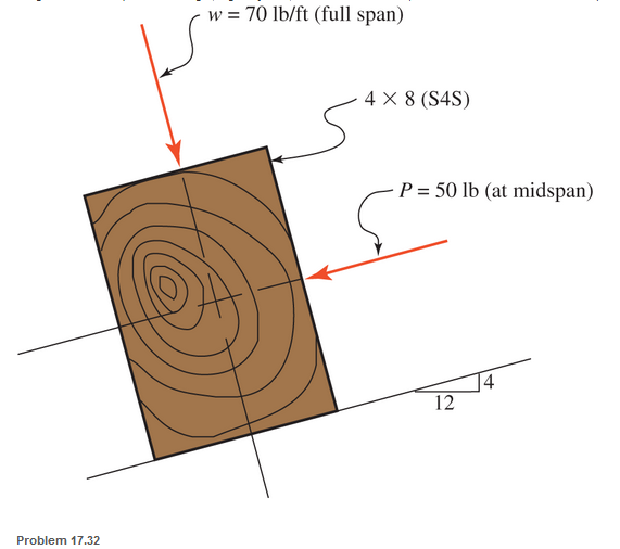
A 4-in.-by-8-in. (S4S) Douglas fir timber beam is supported on a 16-ft simple span and is subjected to the loads shown. The uniformly distributed line load does not include the weight of the beam (the beam weight. a gravity load, should be considered). Find the maximum tensile and compressive stresses.
Expert Solution & Answer
Want to see the full answer?
Check out a sample textbook solution
Students have asked these similar questions
A cast iron beam is of T-section as shown in Fig. The beam is simply supported on a span of 6 m. The beam carries a uniformly distributed load of 2 kN/m length on the entire span. Determine the maximum tensile and maximum compressive stresses.
For a steel circular cantilever beam, 10mm in diameter, 700mm in length with an applied load of 7.848N in the free end, produce a sketch showing the distribution of stresses across the beam section for an applied moment of
M=(3/4My+1/3Mp). Where My=24543.5 N.mm and Mp=41666.66667 N.mm and yeild stregth of material is 250Mpa.
Cheers
A beam of rectangular cross-section is 64 mm broad, 100 mm deep, and 1.6 m long. It is simply supported at each end and carries a concentrated load of 10 kN at its mid-length. Neglecting the weight of the beam, find the maximum stress in the material.
Chapter 17 Solutions
EBK APPLIED STATICS AND STRENGTH OF MAT
Ch. 17 - Prob. 17.1PCh. 17 - A horizontal 30-ft simple span beam is supported...Ch. 17 - A 1-in.-by-4-in, steel bar is subjected to the...Ch. 17 - A W410100 structural steel wide-flange section is...Ch. 17 - A W1272 structural steel wide-flange section is...Ch. 17 - A solid steel shaft 3 in. in diameter and 4 ft...Ch. 17 - A short compression member is subjected to a...Ch. 17 - With reference to Problem 17.7, calculate the...Ch. 17 - A section of a 51-mm-diameter standard-weight...Ch. 17 - For the pipe of Problem 17.9, compute the maximum...
Ch. 17 - A concrete pedestal is in the shape of a cube and...Ch. 17 - 17.12 For the pedestal of Problem 17.11, assume...Ch. 17 - 17.13 Rework Problem 17.11, but assume that the...Ch. 17 - A 12-in-square concrete pedestal is subjected to a...Ch. 17 - 17.15 A short compression member is subjected to a...Ch. 17 - A rectangular concrete footing, 4 ft by 8 ft in...Ch. 17 - The bending and shear stresses developed at a...Ch. 17 - Stresses developed at a point in a machine part...Ch. 17 - Calculate the principal stresses at points A and B...Ch. 17 - 17.20 Rework Problem 17.19 using P = 8000 lb and...Ch. 17 - 17.21 A 1-in.-square steel bar is subjected to an...Ch. 17 - 17.22 A bar having a cross-sectional area of 6...Ch. 17 - Rework Problem 17.22, changing the load to a...Ch. 17 - Solve Problem l7.17 using Mohr’s circle.Ch. 17 - For the elements shown in Problem 17.18, use...Ch. 17 - Solve Problem 17.19 using Mohr’s circle.Ch. 17 - In Problem 17.19, change the load to 8000 lb and...Ch. 17 - For the following computer problems, any...Ch. 17 - For the following computer problems, any...Ch. 17 - For the following computer problems, any...Ch. 17 - For the following computer problems, any...Ch. 17 - A 4-in.-by-8-in. (S4S) Douglas fir timber beam is...Ch. 17 - A horizontal flexural member (a girt) in the wall...Ch. 17 - A simply supported W1850 structural steel...Ch. 17 - A steel link in a machine is designed to avoid...Ch. 17 - 17.36 An 8-in-square (S4S) vertical timber post is...Ch. 17 - A short 3-in.-square steel bar with a...Ch. 17 - A timber member 150 mm by 250 mm (S4S) is loaded...Ch. 17 - A concrete wall 8 ft high and 3 ft thick is...Ch. 17 - 17.40 A short compression member is subjected to a...Ch. 17 - 17.41 Calculate the maximum eccentric load that...Ch. 17 - A short compression member is subjected to two...Ch. 17 - 17.43 Calculate the force P that may be applied to...Ch. 17 - 17.44 A load of 1000 lb is supported on a...Ch. 17 - 17.45 A short compression member is subjected to...Ch. 17 - 17.46 A structural steel wide-flange section is...Ch. 17 - 17.47 A cast-iron frame for a piece of industrial...Ch. 17 - 17.48 The assembly shown is used in a machine. It...Ch. 17 - 17.49 A 50-mm-diameter solid steel shaft is...Ch. 17 - An element of a machine member is subjected to the...Ch. 17 - 17.51 A short-span cantilever built-up beam has...Ch. 17 - Solve Problem 17.50 using Mohr’s circle.Ch. 17 - 17.53 A cantilever beam is subjected to an...Ch. 17 - A 6-in.-diameter solid shaft is subjected to a...Ch. 17 - Rework parts (b) and (c) of Example 17.7 using...
Knowledge Booster


Learn more about
Need a deep-dive on the concept behind this application? Look no further. Learn more about this topic, mechanical-engineering and related others by exploring similar questions and additional content below.Similar questions
- Consider a 2-meter simply supported beam with a circular cross section. The beam is subjected to a point load of 1000N at its center. What is the minimum diameter (in meters) of the beam necessary for the normal stress to remain below 10MPa?arrow_forwardThe cross section of a reinforced concrete beam is shown below. It has a modular ratio of 15. If the allowable compressive stress in the concrete is 6 MPa and the allowable tensile stress in the steel is 120 MPa, determine diameter of the three reinforcing steel rods to make the beam an economic section.arrow_forwardAn electric power transmission pole is 12 m above ground level and embedded 2 m into the ground. The butt diameter is 450 mm and the tip diameter (the top of the pole) is 320 mm. The weight of the pole, cross arms, and wires is 33 kN. Assuming the pole transmits the load as a point load, find the change in vertical stress in kPa at 1m depth.arrow_forward
- A brass strip, 50 mm x 12 mm in section, is riveted to a steel strip, Figure (22) 65 mm x 10 mm in section, to form a compound beam of total depth 22 mm, the brass strip being on top and the beam section being symmetrical about the vertical axis. The beam is simply supported on a span of 1.3 m and carries a load of 2 kN at mid-span. (a) Determine the maximum stresses in each of the materials owing to bending. (b) Make a diagram showing the distribution of bending stress over the depth of the beam. Take E for steel = 200 GN/m² and E for brass = 100 GN/m². Ans.( 0) = 130 MN/m²; 0, = 162.9 MN/m²]arrow_forwardQuestion 1 A thin-walled cylindrical pressure vessel of radius r is subjected simultaneously to internal gas pressure P and a compressive force F acting at the ends (see figure 1) (a) what should be the magnitude of the force F in order to produce pure shear in the wall of the cylinder (b) compute the required thickness of the vessel if force F=190 kN, internal pressure P=12MPa, inner diameter=200mm, and allowable normal and shear stresses are 110MPa and 60MPa, respectively?arrow_forwardA simply supported I beam is 12 metres long with a midspan point load of 15 kN and a uniformly distributed load of 5 kN/m along its full length (see the sketch below). The I beam consists of a web of 220 mm x 25 mm and two flanges of 180 mm x 20 mm. Find all the key shear stresses and complete the following answer sectionsarrow_forward
- A round beam of length 14-in is simply supported at A and D. The beam is loaded in torsion and with transverse loads. The diameter of the beam is 1.5-in. Calculate the principal stresses and the max shear stress at the mostcritical point in the beam.arrow_forwardAnalyze the beam for stresses at point A and B due to combined effect of loading. Force F is equal to 5000 lbs and P is equal to 3500 lbs.arrow_forwardCalculate the end bearing length (in.) required for a 10-in.-by-16-in. timber beam (dressed) that is supported on a reinforced concrete wall as shown. The beam reaction is 18,000 lb and the allowable compressive stress perpendicular to the grain for the timer member is 400 psi. (Unit: in.)arrow_forward
- A simply supported wood beam is subjected to uniformly distributed load q. The width of the beam is 6 in, and the height is 8 in. Determine the normal stress and the shear stress at point C. Show these stresses on a sketch of a stress element at point C.arrow_forwardA circular shaft is subjected to combined loads of bending M and torque T. With the help of Mohr's circle diagram, represent the stresses on an element of the shaft surface. From this diagram or by calculation, find the maximum shear stress due to the combined effect of these gradually applied loads of M and T.arrow_forwardNEED HELP PLEASE ASAP!! A wood pole of solid circular cross section () is subjected to a triangular distributed horizontal force of peak intensity (see the figure). The length of the pole is , and the allowable stresses in the wood are in bending and in shear.arrow_forward
arrow_back_ios
SEE MORE QUESTIONS
arrow_forward_ios
Recommended textbooks for you
 Mechanics of Materials (MindTap Course List)Mechanical EngineeringISBN:9781337093347Author:Barry J. Goodno, James M. GerePublisher:Cengage Learning
Mechanics of Materials (MindTap Course List)
Mechanical Engineering
ISBN:9781337093347
Author:Barry J. Goodno, James M. Gere
Publisher:Cengage Learning
Mechanics of Materials Lecture: Beam Design; Author: UWMC Engineering;https://www.youtube.com/watch?v=-wVs5pvQPm4;License: Standard Youtube License