
EBK APPLIED STATICS AND STRENGTH OF MAT
6th Edition
ISBN: 8220101337603
Author: Spiegel
Publisher: YUZU
expand_more
expand_more
format_list_bulleted
Concept explainers
Videos
Textbook Question
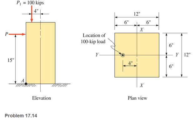
Chapter 17, Problem 17.14P
A 12-in-square concrete pedestal is subjected to a 100-kip vertical eccentric load applied on the Y-Y axis, as shown. Determine the required magnitude of the horizontal load P (also in the vertical plane through the Y-Y axis) for a combined stress of zero at point A.
Expert Solution & Answer
Want to see the full answer?
Check out a sample textbook solution
Students have asked these similar questions
The 1.4-kip load P is supported by two wooden members of uniform cross section that are joined by the simple glued scarf splice shown.Determine the normal and shearing stresses in the glued splice.
A 1600-lb-in. couple is applied to a wooden beam, of rectangular cross section 1.5 by 3.5 in., in a plane forming an angle of 308 with the vertical (Fig. ). Determine (a) the maximum stress in the beam and (b) the angle that the neutral surface forms with the horizontal plane
A solid steel crank has an outside diameter of 32.95 mm. For the loadings shown, determine the normal stress σx on the top surface of the crank at point H.
Chapter 17 Solutions
EBK APPLIED STATICS AND STRENGTH OF MAT
Ch. 17 - Prob. 17.1PCh. 17 - A horizontal 30-ft simple span beam is supported...Ch. 17 - A 1-in.-by-4-in, steel bar is subjected to the...Ch. 17 - A W410100 structural steel wide-flange section is...Ch. 17 - A W1272 structural steel wide-flange section is...Ch. 17 - A solid steel shaft 3 in. in diameter and 4 ft...Ch. 17 - A short compression member is subjected to a...Ch. 17 - With reference to Problem 17.7, calculate the...Ch. 17 - A section of a 51-mm-diameter standard-weight...Ch. 17 - For the pipe of Problem 17.9, compute the maximum...
Ch. 17 - A concrete pedestal is in the shape of a cube and...Ch. 17 - 17.12 For the pedestal of Problem 17.11, assume...Ch. 17 - 17.13 Rework Problem 17.11, but assume that the...Ch. 17 - A 12-in-square concrete pedestal is subjected to a...Ch. 17 - 17.15 A short compression member is subjected to a...Ch. 17 - A rectangular concrete footing, 4 ft by 8 ft in...Ch. 17 - The bending and shear stresses developed at a...Ch. 17 - Stresses developed at a point in a machine part...Ch. 17 - Calculate the principal stresses at points A and B...Ch. 17 - 17.20 Rework Problem 17.19 using P = 8000 lb and...Ch. 17 - 17.21 A 1-in.-square steel bar is subjected to an...Ch. 17 - 17.22 A bar having a cross-sectional area of 6...Ch. 17 - Rework Problem 17.22, changing the load to a...Ch. 17 - Solve Problem l7.17 using Mohr’s circle.Ch. 17 - For the elements shown in Problem 17.18, use...Ch. 17 - Solve Problem 17.19 using Mohr’s circle.Ch. 17 - In Problem 17.19, change the load to 8000 lb and...Ch. 17 - For the following computer problems, any...Ch. 17 - For the following computer problems, any...Ch. 17 - For the following computer problems, any...Ch. 17 - For the following computer problems, any...Ch. 17 - A 4-in.-by-8-in. (S4S) Douglas fir timber beam is...Ch. 17 - A horizontal flexural member (a girt) in the wall...Ch. 17 - A simply supported W1850 structural steel...Ch. 17 - A steel link in a machine is designed to avoid...Ch. 17 - 17.36 An 8-in-square (S4S) vertical timber post is...Ch. 17 - A short 3-in.-square steel bar with a...Ch. 17 - A timber member 150 mm by 250 mm (S4S) is loaded...Ch. 17 - A concrete wall 8 ft high and 3 ft thick is...Ch. 17 - 17.40 A short compression member is subjected to a...Ch. 17 - 17.41 Calculate the maximum eccentric load that...Ch. 17 - A short compression member is subjected to two...Ch. 17 - 17.43 Calculate the force P that may be applied to...Ch. 17 - 17.44 A load of 1000 lb is supported on a...Ch. 17 - 17.45 A short compression member is subjected to...Ch. 17 - 17.46 A structural steel wide-flange section is...Ch. 17 - 17.47 A cast-iron frame for a piece of industrial...Ch. 17 - 17.48 The assembly shown is used in a machine. It...Ch. 17 - 17.49 A 50-mm-diameter solid steel shaft is...Ch. 17 - An element of a machine member is subjected to the...Ch. 17 - 17.51 A short-span cantilever built-up beam has...Ch. 17 - Solve Problem 17.50 using Mohr’s circle.Ch. 17 - 17.53 A cantilever beam is subjected to an...Ch. 17 - A 6-in.-diameter solid shaft is subjected to a...Ch. 17 - Rework parts (b) and (c) of Example 17.7 using...
Knowledge Booster


Learn more about
Need a deep-dive on the concept behind this application? Look no further. Learn more about this topic, mechanical-engineering and related others by exploring similar questions and additional content below.Similar questions
- The axial force in the column supporting the timber beam shown is P = 20 kips. Determine the smallest allowable length L of the bearing plate if the bearing stress in the timber is not to exceed 400 psi.arrow_forwardA vertical force P = 15 kip is applied at point C located on the axis of symmetry of the cross-section of a short column. Given that y = 4.8 in, determine: a. The stress at points A and B b. The location of the neutral axis Note that point C where the force is applied is not the centroid of the cross sectionarrow_forwardA rod is composed of an aluminum section rigidly attached between steel and bronze sections, as shown. Axial loads are applied at the positions indicated. If P = 4000 lb and the cross sectional area of the rod is 0.5 in2, determine the stress in the aluminum section.arrow_forward
- A couple of magnitude M is applied to a square bar of side a/v3. For each of the orientations shown, determine the maximum stress and the curvature of the bar.arrow_forwardTwo forkend pieces are to be joined together by a single steel pin of 25mmdiameter and they are required to transmit 50 kN. Determine the minimum crosssectional area of material required in one branch of either fork if the stress in the forkmaterial is not to exceed 180 MN/m2. What will be the maximum shear stress in thepin?arrow_forwardTwo forces P can be applied separately or at the same time to a plate that is welded to a solid circular bar of radius r. Determine the largest compressive stress in the circular bar (a) when both forces are applied, (b) when only one of the forces is applied.arrow_forward
- The outside diameter of the steel pipe shown is 220 mm and its wall thickness is 6.0 mm. The upper bearing plate has the same width as the reinforced concrete beam it supports. The total load on the column by the reinforced concrete beam is 550 kN. Determine: A. The length L of the rectangular upper bearing plate if its width is 275 mm. and the average bearing stress between the steel plate and the reinforced concrete beam is not to exceed 6.2 MPa.arrow_forwardDetermine the maximum compressive stress in the bracket at section a–a when the load P = 52 kN is applied at x = 300 mm.arrow_forwardA 150mm x 30mm x 250mm central wooden block is glued between cantilevered brackets 200mm x 50mm each as shown. If the Shear Stress of the glued joint can NOT exceed 4N/mm2, find the Vertical load that can be applied on the central plank.arrow_forward
- The frame shown in Figure 5 consists of four wooden members, ABC, DEF,BE, and CF. Knowing that each member has 50 mm x 100 mm rectangularcross section and that each pin has a 12 mm diameter. Determine themaximum value of the average stress (a) in member BE and (b) in member CF.arrow_forwardA) Using the ultimate stress found earlier, determine the minimum diameter of post BD required for the post not to fail. B) Using the ultimate stress found earlier, determine the minimum diameter of post CE required for the post not to fail.arrow_forward3. A composite bar consists of an aluminum section rigidly fastened between bronze section and steel section as shown. Axial load as applied at the position indicated. Determine the stress in each section.arrow_forward
arrow_back_ios
SEE MORE QUESTIONS
arrow_forward_ios
Recommended textbooks for you
 Elements Of ElectromagneticsMechanical EngineeringISBN:9780190698614Author:Sadiku, Matthew N. O.Publisher:Oxford University Press
 Mechanics of Materials (10th Edition)Mechanical EngineeringISBN:9780134319650Author:Russell C. HibbelerPublisher:PEARSON
 Thermodynamics: An Engineering ApproachMechanical EngineeringISBN:9781259822674Author:Yunus A. Cengel Dr., Michael A. BolesPublisher:McGraw-Hill Education
 Control Systems EngineeringMechanical EngineeringISBN:9781118170519Author:Norman S. NisePublisher:WILEY
 Mechanics of Materials (MindTap Course List)Mechanical EngineeringISBN:9781337093347Author:Barry J. Goodno, James M. GerePublisher:Cengage Learning
 Engineering Mechanics: StaticsMechanical EngineeringISBN:9781118807330Author:James L. Meriam, L. G. Kraige, J. N. BoltonPublisher:WILEY
Elements Of Electromagnetics
Mechanical Engineering
ISBN:9780190698614
Author:Sadiku, Matthew N. O.
Publisher:Oxford University Press
Mechanics of Materials (10th Edition)
Mechanical Engineering
ISBN:9780134319650
Author:Russell C. Hibbeler
Publisher:PEARSON
Thermodynamics: An Engineering Approach
Mechanical Engineering
ISBN:9781259822674
Author:Yunus A. Cengel Dr., Michael A. Boles
Publisher:McGraw-Hill Education
Control Systems Engineering
Mechanical Engineering
ISBN:9781118170519
Author:Norman S. Nise
Publisher:WILEY
Mechanics of Materials (MindTap Course List)
Mechanical Engineering
ISBN:9781337093347
Author:Barry J. Goodno, James M. Gere
Publisher:Cengage Learning
Engineering Mechanics: Statics
Mechanical Engineering
ISBN:9781118807330
Author:James L. Meriam, L. G. Kraige, J. N. Bolton
Publisher:WILEY
EVERYTHING on Axial Loading Normal Stress in 10 MINUTES - Mechanics of Materials; Author: Less Boring Lectures;https://www.youtube.com/watch?v=jQ-fNqZWrNg;License: Standard YouTube License, CC-BY