
EBK APPLIED STATICS AND STRENGTH OF MAT
6th Edition
ISBN: 8220101337603
Author: Spiegel
Publisher: YUZU
expand_more
expand_more
format_list_bulleted
Videos
Textbook Question
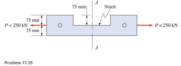
Chapter 17, Problem 17.35SP
A steel link in a machine is designed to avoid interference with other moving parts. The link is 100 mm thick. The cross-sectional area of the link is reduced by one-half at section A-A as shown. Compute the maximum tensile stress developed across section A-A. Neglect any stress concentrations.
Expert Solution & Answer
Want to see the full answer?
Check out a sample textbook solution
Students have asked these similar questions
Calculate the normal stress (in Pa) at point A of the bracket caused by the 11023 N force.
Calculate the normal stresses at points A and B of the bracket caused by the 30-kN force.
Calculate the maximum and minimum normal stresses experienced by the lever indicated in the image.
Chapter 17 Solutions
EBK APPLIED STATICS AND STRENGTH OF MAT
Ch. 17 - Prob. 17.1PCh. 17 - A horizontal 30-ft simple span beam is supported...Ch. 17 - A 1-in.-by-4-in, steel bar is subjected to the...Ch. 17 - A W410100 structural steel wide-flange section is...Ch. 17 - A W1272 structural steel wide-flange section is...Ch. 17 - A solid steel shaft 3 in. in diameter and 4 ft...Ch. 17 - A short compression member is subjected to a...Ch. 17 - With reference to Problem 17.7, calculate the...Ch. 17 - A section of a 51-mm-diameter standard-weight...Ch. 17 - For the pipe of Problem 17.9, compute the maximum...
Ch. 17 - A concrete pedestal is in the shape of a cube and...Ch. 17 - 17.12 For the pedestal of Problem 17.11, assume...Ch. 17 - 17.13 Rework Problem 17.11, but assume that the...Ch. 17 - A 12-in-square concrete pedestal is subjected to a...Ch. 17 - 17.15 A short compression member is subjected to a...Ch. 17 - A rectangular concrete footing, 4 ft by 8 ft in...Ch. 17 - The bending and shear stresses developed at a...Ch. 17 - Stresses developed at a point in a machine part...Ch. 17 - Calculate the principal stresses at points A and B...Ch. 17 - 17.20 Rework Problem 17.19 using P = 8000 lb and...Ch. 17 - 17.21 A 1-in.-square steel bar is subjected to an...Ch. 17 - 17.22 A bar having a cross-sectional area of 6...Ch. 17 - Rework Problem 17.22, changing the load to a...Ch. 17 - Solve Problem l7.17 using Mohr’s circle.Ch. 17 - For the elements shown in Problem 17.18, use...Ch. 17 - Solve Problem 17.19 using Mohr’s circle.Ch. 17 - In Problem 17.19, change the load to 8000 lb and...Ch. 17 - For the following computer problems, any...Ch. 17 - For the following computer problems, any...Ch. 17 - For the following computer problems, any...Ch. 17 - For the following computer problems, any...Ch. 17 - A 4-in.-by-8-in. (S4S) Douglas fir timber beam is...Ch. 17 - A horizontal flexural member (a girt) in the wall...Ch. 17 - A simply supported W1850 structural steel...Ch. 17 - A steel link in a machine is designed to avoid...Ch. 17 - 17.36 An 8-in-square (S4S) vertical timber post is...Ch. 17 - A short 3-in.-square steel bar with a...Ch. 17 - A timber member 150 mm by 250 mm (S4S) is loaded...Ch. 17 - A concrete wall 8 ft high and 3 ft thick is...Ch. 17 - 17.40 A short compression member is subjected to a...Ch. 17 - 17.41 Calculate the maximum eccentric load that...Ch. 17 - A short compression member is subjected to two...Ch. 17 - 17.43 Calculate the force P that may be applied to...Ch. 17 - 17.44 A load of 1000 lb is supported on a...Ch. 17 - 17.45 A short compression member is subjected to...Ch. 17 - 17.46 A structural steel wide-flange section is...Ch. 17 - 17.47 A cast-iron frame for a piece of industrial...Ch. 17 - 17.48 The assembly shown is used in a machine. It...Ch. 17 - 17.49 A 50-mm-diameter solid steel shaft is...Ch. 17 - An element of a machine member is subjected to the...Ch. 17 - 17.51 A short-span cantilever built-up beam has...Ch. 17 - Solve Problem 17.50 using Mohr’s circle.Ch. 17 - 17.53 A cantilever beam is subjected to an...Ch. 17 - A 6-in.-diameter solid shaft is subjected to a...Ch. 17 - Rework parts (b) and (c) of Example 17.7 using...
Knowledge Booster


Learn more about
Need a deep-dive on the concept behind this application? Look no further. Learn more about this topic, mechanical-engineering and related others by exploring similar questions and additional content below.Similar questions
- circular tube AB is fixed at one end andfree at the other end. The tube is subjected to axialforce at joint B. If the outer diameter of the tube is 75 mm and the thickness is 19 mm, calculate the max-imum normal stress in the tube.arrow_forwardTo avoid interference, a link in a machine is designed so that its cross-sectional area is reduced one half at section A-B as shown below. If the thickness of the link is 50 mm, compute the maximum force P that can be applied if the maximum normal stress on section A-B is limited to 80 MPa.arrow_forwardFor the pin connection shown, determine the normal stress acting on the gross area, the normal stress acting on the net area, the shear stress in the pin, and the bearing stress in the steel plate at the pin.arrow_forward
- A cylindrical steel pressure vessel 250 mm radius with a thickness of 20 mm, is subjected to an internal pressure of 4.5 MN/m². Calculate the tangential stress in the steel.arrow_forwardA utility hook is formed from a round rod of diameter dinto the geometry as shown below. What are the stresses at the inner and outer points at section A-A if L= 250 mm, Di= 75 mm. Assume diameter 5 mm ≤ d≤ 35 mm and force F to be 1658 N.arrow_forwardAn aluminum wire 3.0 m in length and 4.0 mm in diameter supports a 1000 N mass. Determine the stress in the wire.arrow_forward
- A circular tube AB is fixed at one end and free at the other end. The tubeis subjected to axialforce at joint B. If the outer diameter of the tube is 3 in, and thethickness is 3/4 in., calculate the maximum normal stress in the tubearrow_forwardThe drill shown is jammed in the wall and is subjected to the torque and force shown in the diagram. Determine the normal stress (in MPa) at point A on the cross section of the drill bit at section a−a.arrow_forwardFind the stresss in the left rod after its lower end is attached to the support.arrow_forward
- Three round bars welded together are axially loaded as shown. Find the normal stress in each bar if P=15 kNarrow_forwardFind normal and shearing stresses at point A .And construct the state of stress at Aarrow_forwardCompute the tensile stress for the rod shown in Fig. 1 at section A-A, the shearing stress across section B, the compressive stress between the pin and the rod, and the compressive stress between the pin and the yoke. Given n = 1 (3 / 4) in., a = (15 / 32) in., e = (27 / 32) in., b = (15 / 16) in., d = (19 / 32) in., f = 1".arrow_forward
arrow_back_ios
SEE MORE QUESTIONS
arrow_forward_ios
Recommended textbooks for you
 Elements Of ElectromagneticsMechanical EngineeringISBN:9780190698614Author:Sadiku, Matthew N. O.Publisher:Oxford University Press
 Mechanics of Materials (10th Edition)Mechanical EngineeringISBN:9780134319650Author:Russell C. HibbelerPublisher:PEARSON
 Thermodynamics: An Engineering ApproachMechanical EngineeringISBN:9781259822674Author:Yunus A. Cengel Dr., Michael A. BolesPublisher:McGraw-Hill Education
 Control Systems EngineeringMechanical EngineeringISBN:9781118170519Author:Norman S. NisePublisher:WILEY
 Mechanics of Materials (MindTap Course List)Mechanical EngineeringISBN:9781337093347Author:Barry J. Goodno, James M. GerePublisher:Cengage Learning
 Engineering Mechanics: StaticsMechanical EngineeringISBN:9781118807330Author:James L. Meriam, L. G. Kraige, J. N. BoltonPublisher:WILEY
Elements Of Electromagnetics
Mechanical Engineering
ISBN:9780190698614
Author:Sadiku, Matthew N. O.
Publisher:Oxford University Press
Mechanics of Materials (10th Edition)
Mechanical Engineering
ISBN:9780134319650
Author:Russell C. Hibbeler
Publisher:PEARSON
Thermodynamics: An Engineering Approach
Mechanical Engineering
ISBN:9781259822674
Author:Yunus A. Cengel Dr., Michael A. Boles
Publisher:McGraw-Hill Education
Control Systems Engineering
Mechanical Engineering
ISBN:9781118170519
Author:Norman S. Nise
Publisher:WILEY
Mechanics of Materials (MindTap Course List)
Mechanical Engineering
ISBN:9781337093347
Author:Barry J. Goodno, James M. Gere
Publisher:Cengage Learning
Engineering Mechanics: Statics
Mechanical Engineering
ISBN:9781118807330
Author:James L. Meriam, L. G. Kraige, J. N. Bolton
Publisher:WILEY
Mechanics of Materials Lecture: Beam Design; Author: UWMC Engineering;https://www.youtube.com/watch?v=-wVs5pvQPm4;License: Standard Youtube License