
EBK APPLIED STATICS AND STRENGTH OF MAT
6th Edition
ISBN: 8220101337603
Author: Spiegel
Publisher: YUZU
expand_more
expand_more
format_list_bulleted
Videos
Textbook Question
Chapter 17, Problem 17.16P
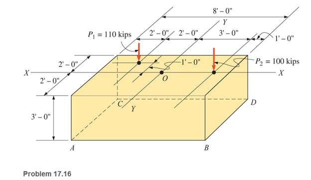
A rectangular concrete footing, 4 ft by 8 ft in plan, is subjected to two column loads, as shown. Calculate the stress (base pressure) at each comer of the footing. Use a concrete unit weight of 150 pcf. Express the answers in pounds per square foot (psf).
Expert Solution & Answer
Want to see the full answer?
Check out a sample textbook solution
Students have asked these similar questions
Two circular rods support the 3800 lbs weight of a space heater in awarehouse. Each rod has a diameter of 0.375 in and carries 1/2 of the totalload. Compute the stress in the rods
Convert a stress of 18,540 lb/in2 to N/m2. Show your calculations.
The rigid bar AB shown below is supported by a steel rod AC having a diameter of 20 mm, and a block. Ignore the weight of AB and AC, and the distributed load on AB is p = 4.0 KN/m. Determine the axial normal stress developed in AC: = ____ MPa. Calculate your answer to 1 decimal place.
Chapter 17 Solutions
EBK APPLIED STATICS AND STRENGTH OF MAT
Ch. 17 - Prob. 17.1PCh. 17 - A horizontal 30-ft simple span beam is supported...Ch. 17 - A 1-in.-by-4-in, steel bar is subjected to the...Ch. 17 - A W410100 structural steel wide-flange section is...Ch. 17 - A W1272 structural steel wide-flange section is...Ch. 17 - A solid steel shaft 3 in. in diameter and 4 ft...Ch. 17 - A short compression member is subjected to a...Ch. 17 - With reference to Problem 17.7, calculate the...Ch. 17 - A section of a 51-mm-diameter standard-weight...Ch. 17 - For the pipe of Problem 17.9, compute the maximum...
Ch. 17 - A concrete pedestal is in the shape of a cube and...Ch. 17 - 17.12 For the pedestal of Problem 17.11, assume...Ch. 17 - 17.13 Rework Problem 17.11, but assume that the...Ch. 17 - A 12-in-square concrete pedestal is subjected to a...Ch. 17 - 17.15 A short compression member is subjected to a...Ch. 17 - A rectangular concrete footing, 4 ft by 8 ft in...Ch. 17 - The bending and shear stresses developed at a...Ch. 17 - Stresses developed at a point in a machine part...Ch. 17 - Calculate the principal stresses at points A and B...Ch. 17 - 17.20 Rework Problem 17.19 using P = 8000 lb and...Ch. 17 - 17.21 A 1-in.-square steel bar is subjected to an...Ch. 17 - 17.22 A bar having a cross-sectional area of 6...Ch. 17 - Rework Problem 17.22, changing the load to a...Ch. 17 - Solve Problem l7.17 using Mohr’s circle.Ch. 17 - For the elements shown in Problem 17.18, use...Ch. 17 - Solve Problem 17.19 using Mohr’s circle.Ch. 17 - In Problem 17.19, change the load to 8000 lb and...Ch. 17 - For the following computer problems, any...Ch. 17 - For the following computer problems, any...Ch. 17 - For the following computer problems, any...Ch. 17 - For the following computer problems, any...Ch. 17 - A 4-in.-by-8-in. (S4S) Douglas fir timber beam is...Ch. 17 - A horizontal flexural member (a girt) in the wall...Ch. 17 - A simply supported W1850 structural steel...Ch. 17 - A steel link in a machine is designed to avoid...Ch. 17 - 17.36 An 8-in-square (S4S) vertical timber post is...Ch. 17 - A short 3-in.-square steel bar with a...Ch. 17 - A timber member 150 mm by 250 mm (S4S) is loaded...Ch. 17 - A concrete wall 8 ft high and 3 ft thick is...Ch. 17 - 17.40 A short compression member is subjected to a...Ch. 17 - 17.41 Calculate the maximum eccentric load that...Ch. 17 - A short compression member is subjected to two...Ch. 17 - 17.43 Calculate the force P that may be applied to...Ch. 17 - 17.44 A load of 1000 lb is supported on a...Ch. 17 - 17.45 A short compression member is subjected to...Ch. 17 - 17.46 A structural steel wide-flange section is...Ch. 17 - 17.47 A cast-iron frame for a piece of industrial...Ch. 17 - 17.48 The assembly shown is used in a machine. It...Ch. 17 - 17.49 A 50-mm-diameter solid steel shaft is...Ch. 17 - An element of a machine member is subjected to the...Ch. 17 - 17.51 A short-span cantilever built-up beam has...Ch. 17 - Solve Problem 17.50 using Mohr’s circle.Ch. 17 - 17.53 A cantilever beam is subjected to an...Ch. 17 - A 6-in.-diameter solid shaft is subjected to a...Ch. 17 - Rework parts (b) and (c) of Example 17.7 using...
Knowledge Booster


Learn more about
Need a deep-dive on the concept behind this application? Look no further. Learn more about this topic, mechanical-engineering and related others by exploring similar questions and additional content below.Similar questions
- A cylinder having an internal diameter of 20 inches and external diameter of 28 inches is subjected to an internal pressure of 8500 psi. If the outer hoop stress is 14 ksi, find the external pressure in psi.arrow_forwardCalculate the stresses on the given round hollow frame.arrow_forwardThe lap joint shown is fastened by five ¾ inch-diameter rivets. The bearing stress in the plates is limited to 10 ksi and the shearing stress in the rivets is 15 ksi. Assume the applied load is equally distributed among the five rivets. The thickness of each plate is ½ in. Calculate the load P based on each stress given. Determine the maximum safe load P that can be applied. Express the loads in kips.arrow_forward
- The homogeneous bar ABC is supported by a pin at C and a cable that runs from A to B around the frictionless pulley at D. Find the stress (in psi) in the cable if its diameter is d = 0.51 in and the weight of the bar is 5298 lb. Round off the final answer to three decimal places.arrow_forwardCalculate the normal stress (in Pa) at point A of the bracket caused by the 11023 N force.arrow_forwardA thin walled spherical shell is subjected to an internal pressure. If the radius of the shell is increased by 1% and the thickness is reduced by 1%, with the internal pressure remaining the same, the percentage change in the circumferential (hoop) stress is.....arrow_forward
- solve compelete sol The assembly in Figure consists of a light rigid bar AB, pinned at O, that is attached to the steel and aluminum rods. In the position shown, bar AB is horizontal and there is a gap, △ = 5 mm, between the lower end of the steel rod and its pin support at C. Compute the stress in the aluminum rod when the lower end of the steel rod is attached to its support.arrow_forwardDetermine the largest weight “W” that can be supported by the two wires AB and AC. The working stresses are 100MPa for AB and 150MPa for AC. The cross sectional area of AB and AC are 400mm2 and 200mm2 Compute “W” due to the stress capacity of AB Compute “W” due to the stress capacity of AC. Determine the safest value of “W”.arrow_forwardThe plate as shown weighing 30 kN is raised by a cable sling. The cable sling has the identical clevis at each end and the pins through these clevises are 25 mm Ø. Determine the shear stress in the pin. Compute the bearing stress between the clevis and the pin if the thickness of the yoke is 25 mmarrow_forward
- The turnbuckles in the diagram shown are tightened until the compression block DB exerts a force of 12,365lb on the beam at B. Member DB is a hollow shaft with an inner diameter of 1.0 inch and outer diameter of 2 inches. Rods AD and CD each have cross-sectional areas of 1.1 square inches. Pin C has a diameter of 0.78 inch. Determine the following: a.The axial stress, in psi, in BD. b.The axial stress, in psi, in CD.c.The shearing stress, in psi, in pin C.arrow_forward5 decimal places 8. A 7-ft diameter spherical tank is subjected to an internal pressure of 24 psf. If the wall thickness is 0.35", determine the tangential stress of the wall in psi.arrow_forwardThe homogeneous bar ABC is supported by a pin at C and a cable that runs from A to B around the frictionless pulley at D. Find the stress (in psi) in the cable if its diameter is d = 0.55 in and the weight of the bar is 5391 lb. Round off the final answer to 3 decimal places.arrow_forward
arrow_back_ios
SEE MORE QUESTIONS
arrow_forward_ios
Recommended textbooks for you
 Elements Of ElectromagneticsMechanical EngineeringISBN:9780190698614Author:Sadiku, Matthew N. O.Publisher:Oxford University Press
 Mechanics of Materials (10th Edition)Mechanical EngineeringISBN:9780134319650Author:Russell C. HibbelerPublisher:PEARSON
 Thermodynamics: An Engineering ApproachMechanical EngineeringISBN:9781259822674Author:Yunus A. Cengel Dr., Michael A. BolesPublisher:McGraw-Hill Education
 Control Systems EngineeringMechanical EngineeringISBN:9781118170519Author:Norman S. NisePublisher:WILEY
 Mechanics of Materials (MindTap Course List)Mechanical EngineeringISBN:9781337093347Author:Barry J. Goodno, James M. GerePublisher:Cengage Learning
 Engineering Mechanics: StaticsMechanical EngineeringISBN:9781118807330Author:James L. Meriam, L. G. Kraige, J. N. BoltonPublisher:WILEY
Elements Of Electromagnetics
Mechanical Engineering
ISBN:9780190698614
Author:Sadiku, Matthew N. O.
Publisher:Oxford University Press
Mechanics of Materials (10th Edition)
Mechanical Engineering
ISBN:9780134319650
Author:Russell C. Hibbeler
Publisher:PEARSON
Thermodynamics: An Engineering Approach
Mechanical Engineering
ISBN:9781259822674
Author:Yunus A. Cengel Dr., Michael A. Boles
Publisher:McGraw-Hill Education
Control Systems Engineering
Mechanical Engineering
ISBN:9781118170519
Author:Norman S. Nise
Publisher:WILEY
Mechanics of Materials (MindTap Course List)
Mechanical Engineering
ISBN:9781337093347
Author:Barry J. Goodno, James M. Gere
Publisher:Cengage Learning
Engineering Mechanics: Statics
Mechanical Engineering
ISBN:9781118807330
Author:James L. Meriam, L. G. Kraige, J. N. Bolton
Publisher:WILEY
Mechanics of Materials Lecture: Beam Design; Author: UWMC Engineering;https://www.youtube.com/watch?v=-wVs5pvQPm4;License: Standard Youtube License