Statics And Mechanics Of Materials, Student Value Edition Plus Mastering Engineering With Pearson Etext -- Access Card Package (5th Edition)
5th Edition
ISBN: 9780134380704
Author: Russell C. Hibbeler
Publisher: PEARSON
expand_more
expand_more
format_list_bulleted
Concept explainers
Videos
Textbook Question
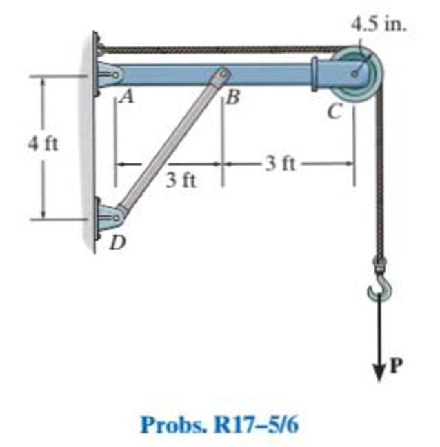
Chapter 17, Problem 6RP
If P = 15 kip, determine the required minimum diameter of the A992 steel solid circular rod BD to the nearest
Expert Solution & Answer
Want to see the full answer?
Check out a sample textbook solution
Students have asked these similar questions
Link OB is 20 mm wide and 10 mm thick and is made from low-carbon steel with Sy= 200 MPa. The pin joints are constructed with
sufficient size and fit to provide good resistance to out-of-plane bending. Determine the factor of safety for out-of-plane buckling.
800 mm
where F=1250 N
B
400 mm
F
The factor of safety for out-of-plane buckling is
Can you answer?
be fastly please
A 6061-T6 aluminum alloy solid circular rod of length 4 m is pinned at one end while fixed at the other end. If it is subjected to an axial load of 15 kN and F.S. = 2 against buckling, determine the minimum required diameter of the rod to the nearest mm
Chapter 17 Solutions
Statics And Mechanics Of Materials, Student Value Edition Plus Mastering Engineering With Pearson Etext -- Access Card Package (5th Edition)
Ch. 17.3 - A 50-in.-long steel rod has a diameter of 1 in....Ch. 17.3 - A 12-ft wooden rectangular column has the...Ch. 17.3 - Prob. 3FPCh. 17.3 - A steel pipe is fixed supported at its ends. If it...Ch. 17.3 - Determine the maximum force P that can be...Ch. 17.3 - The A992 steel rod BC has a diameter of 50 mm and...Ch. 17.3 - Determine the critical buckling load for the...Ch. 17.3 - Prob. 2PCh. 17.3 - The aircraft link is made from an A992 steel rod....Ch. 17.3 - Rigid bars AB and BC are pin connected at B. If...
Ch. 17.3 - A 2014-T6 aluminum alloy column has a length of 6...Ch. 17.3 - Prob. 6PCh. 17.3 - Prob. 7PCh. 17.3 - Prob. 8PCh. 17.3 - A steel column has a length of 9 m and is fixed at...Ch. 17.3 - A steel column has a length of 9 m and is pinned...Ch. 17.3 - The A992 steel angle has a cross-sectional area of...Ch. 17.3 - The 50-mm-diameter C86100 bronze rod is fixed...Ch. 17.3 - Determine the maximum load P the frame can support...Ch. 17.3 - Prob. 14PCh. 17.3 - Prob. 15PCh. 17.3 - An A992 steel W200 46 column of length 9 m is...Ch. 17.3 - Prob. 17PCh. 17.3 - Prob. 18PCh. 17.3 - Prob. 19PCh. 17.3 - Prob. 20PCh. 17.3 - Prob. 21PCh. 17.3 - The deck is supported by the two 40-mm-square...Ch. 17.3 - Prob. 23PCh. 17.3 - Prob. 24PCh. 17.3 - Prob. 25PCh. 17.3 - Prob. 26PCh. 17.3 - Prob. 27PCh. 17.3 - The linkage is made using two A992 steel rods,...Ch. 17.3 - The linkage is made using two A-36 steel rods,...Ch. 17.3 - The linkage is made using two A-36 steel rods,...Ch. 17.3 - The steel bar AB has a rectangular cross section....Ch. 17.3 - Determine if the frame can support a load of P =...Ch. 17.3 - Determine the maximum allowable load P that can be...Ch. 17.3 - Prob. 34PCh. 17.3 - Prob. 35PCh. 17.3 - The members of the truss are assumed to be pin...Ch. 17.3 - The members of the truss are assumed to be pin...Ch. 17.3 - The truss is made from A992 steel bars, each of...Ch. 17.3 - The truss is made from A992 steel bars, each of...Ch. 17.3 - The steel bar AB of the frame is assumed to be pin...Ch. 17.3 - Prob. 41PCh. 17.3 - Prob. 42PCh. 17.3 - Prob. 43PCh. 17.3 - Prob. 44PCh. 17.3 - Consider an ideal column as in Fig. 1710d, having...Ch. 17.4 - Prob. 46PCh. 17.4 - Prob. 47PCh. 17.4 - The W10 12 structural A-36 steel column is used...Ch. 17.4 - The aluminum column is fixed at the bottom and...Ch. 17.4 - Prob. 50PCh. 17.4 - The aluminum rod is fixed at its base and free and...Ch. 17.4 - Prob. 52PCh. 17.4 - Prob. 53PCh. 17.4 - Prob. 54PCh. 17.4 - The wood column is pinned at its base and top....Ch. 17.4 - Prob. 56PCh. 17.4 - Prob. 57PCh. 17.4 - Prob. 58PCh. 17.4 - Prob. 59PCh. 17.4 - Prob. 60PCh. 17.4 - Prob. 61PCh. 17.4 - Prob. 62PCh. 17.4 - The W14 53 column is fixed at its base and free...Ch. 17.4 - Prob. 64PCh. 17 - The wood column is 4 m long and is required to...Ch. 17 - Prob. 2RPCh. 17 - A steel column has a length of 5 m and is free at...Ch. 17 - Prob. 4RPCh. 17 - Prob. 5RPCh. 17 - If P = 15 kip, determine the required minimum...Ch. 17 - Prob. 7RPCh. 17 - The W200 46 wide-flange A992-steel column can be...Ch. 17 - The wide-flange A992 steel column has the cross...Ch. 17 - The wide-flange A992 steel column has the cross...
Knowledge Booster


Learn more about
Need a deep-dive on the concept behind this application? Look no further. Learn more about this topic, mechanical-engineering and related others by exploring similar questions and additional content below.Similar questions
- The linkage is made using two A-36 steel rods, each having a circular cross section. Determine the diameter of each rod to the nearest 1 8 in. that will support the 900-lb load. Assume that the rods are pin connected at their ends. Use a factor of safety with respect to buckling of F.S. = 1.8.arrow_forwardA 6061-T6 aluminum alloy solid circular rod of length 4 m is pinned at both of its ends. If it is subjected to an axial load of 15 kN and F.S. = 2 against buckling, determine the minimum required diameter of the rod to the nearest mm.arrow_forwardThe L-2 Tool Steel link is pinned as shown. Determine the critical buckling load in each casearrow_forward
- A long, slender structural aluminum [E = 69 GPa] flanged shape is used as al = 9.2-m-long column. The column is supported in the x direction at base A and pinned at ends A and C against translation in the y and z directions. Lateral support is provided to the column so that deflection in the x-z plane is restrained at mid-height B; however, the column is free to deflect in the x-y plane at B. Assume that b; = 102 mm, d = 122 mm, t; = 8 mm, and tw = 6 mm. Determine the maximum compressive load P the column can support if a factor of safety of 2.9 is required. In your analysis, consider the possibility that buckling could occur about either the strong axis (i.e., the z axis) or the weak axis (i.e., the y axis) of the aluminum column. P bf C L d Lateral B bracing Larrow_forwardWhat is the maximum force P that can be applied to the handle so that the steel control rod AB does not buckle? The rod has a diameter of 0.25 m. It is pin connected at its ends. E =76 MPa. Select 3m 2m one: 10.65 A kN O 8.49 kN 5 m 5.05 kN O 3.84 kN O 14.03 kNarrow_forwardSolve carefully and circle your answer with the correct units ! Write clearly use image belowarrow_forward
- Determine the effective length and the critical load before buckling for the column in the diagram, El is constant.arrow_forwardIf load P = 20.3 kips, determine the normal force in bar (1). D A 6 ft 43.8 kips 31.0 kips 33.8 kips 20.3 kips 39.3 kips B (1) 4 ftarrow_forwardA column consists of a 2.5 m long hollow tube with an outside diameter equal to 1.5 times that of the inside diameter. The column must carry an axial load of 40 KN without buckling. Use a factor of safety of 5 and calculate the dimensions of the tube if one end is fixed and the other end is free. Use the Euler formula and take ?=200 ???.arrow_forward
- P=17000000arrow_forward• Bars (1) have a cross-sectional area of A₁ = 0.65 in.2 and a length, L₁= 7 ft. • Bars (1) are made of cast iron with an elastic modulus of E₁ = 24,000 ksi, a coefficient of thermal expansion, a₁ = 12.3 x 10⁻⁶/°F and yield strength of oy = 120 ksi. • Bar (2) has a cross-sectional area of A₂ = 1.45 in.² and a length, L₂ = 5.5 ft. • Bar (2) is made of stainless steel with a coefficient of thermal expansion, a₂ = 10.6 × 10⁻⁶/°F. • The stress-strain diagram provided below presents the results of the stainless steel's (i.e., Bar (2)) bar tension test. • There is a gap of A = 0.1 in. in the connection at B and a = 3 ft. • All bars are unstressed before a load P = 12 kips is applied and the temperature increases by AT = 40°F. Stress-strain diagram for stainless steel bar: (1) a Stress (ksi) L2 Rigid bar 120 100 80 60 40 20 0 0 0 B (2) P a (1) C Upper scale L₁ Connection details at node C Lower scale. C 0.025 0.050 0.075 0.100 0.125 0.150 0.175 0.006 0.008 0.010 0.012 0.014 0.002 0.004 Strain…arrow_forwardAn L-2 steel link in a forging machine is pin connected to the forks at its ends as shown. Determine the maximum load Pit can carry without buckling. Use a factor of safety with respect to buckling of F.S. = 1.75. Note from the figure on the left that the ends are pinned for buckling, whereas from the figure on the right the ends are fixed. P P 1.5 in. 24 in. P P 0.5 in.arrow_forward
arrow_back_ios
SEE MORE QUESTIONS
arrow_forward_ios
Recommended textbooks for you
 Elements Of ElectromagneticsMechanical EngineeringISBN:9780190698614Author:Sadiku, Matthew N. O.Publisher:Oxford University Press
 Mechanics of Materials (10th Edition)Mechanical EngineeringISBN:9780134319650Author:Russell C. HibbelerPublisher:PEARSON
 Thermodynamics: An Engineering ApproachMechanical EngineeringISBN:9781259822674Author:Yunus A. Cengel Dr., Michael A. BolesPublisher:McGraw-Hill Education
 Control Systems EngineeringMechanical EngineeringISBN:9781118170519Author:Norman S. NisePublisher:WILEY
 Mechanics of Materials (MindTap Course List)Mechanical EngineeringISBN:9781337093347Author:Barry J. Goodno, James M. GerePublisher:Cengage Learning
 Engineering Mechanics: StaticsMechanical EngineeringISBN:9781118807330Author:James L. Meriam, L. G. Kraige, J. N. BoltonPublisher:WILEY
Elements Of Electromagnetics
Mechanical Engineering
ISBN:9780190698614
Author:Sadiku, Matthew N. O.
Publisher:Oxford University Press
Mechanics of Materials (10th Edition)
Mechanical Engineering
ISBN:9780134319650
Author:Russell C. Hibbeler
Publisher:PEARSON
Thermodynamics: An Engineering Approach
Mechanical Engineering
ISBN:9781259822674
Author:Yunus A. Cengel Dr., Michael A. Boles
Publisher:McGraw-Hill Education
Control Systems Engineering
Mechanical Engineering
ISBN:9781118170519
Author:Norman S. Nise
Publisher:WILEY
Mechanics of Materials (MindTap Course List)
Mechanical Engineering
ISBN:9781337093347
Author:Barry J. Goodno, James M. Gere
Publisher:Cengage Learning
Engineering Mechanics: Statics
Mechanical Engineering
ISBN:9781118807330
Author:James L. Meriam, L. G. Kraige, J. N. Bolton
Publisher:WILEY
Column buckling; Author: Amber Book;https://www.youtube.com/watch?v=AvvaCi_Nn94;License: Standard Youtube License