
Concept explainers
Videos
The essential features of the gyrocompass are shown. The rotor spins at the rate
(a) Show that the equations of motion of the gyrocompass are
where ωz is the rectangular component of the total angular velocity ω along the axis of the rotor, and I and I′ are the moments of inertia of the rotor with respect to its axis of symmetry and a transverse axis through O, respectively.
(b) Neglecting the term containing
and that the axis of the gyrocompass oscillates about the north–south direction.
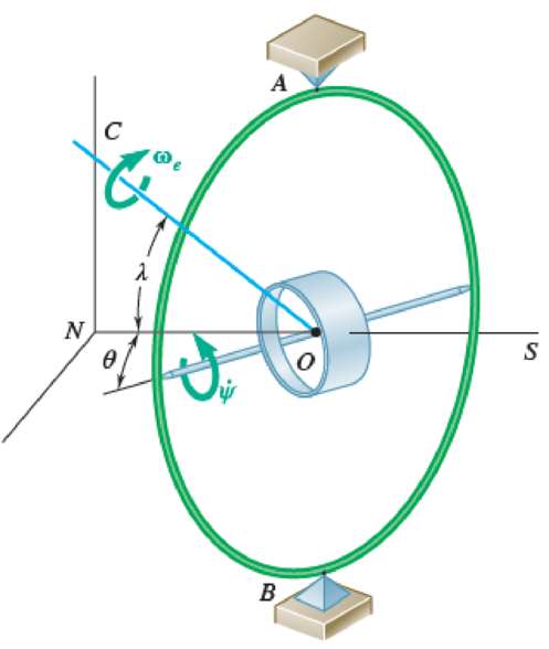
Fig. P18.158
Want to see the full answer?
Check out a sample textbook solution
Chapter 18 Solutions
Vector Mechanics for Engineers: Statics and Dynamics


- To be able to develop an equation relating the linear distance between moving bodies to the angular position and velocity of the first or driving body and to use this relationship to derive the function for absolute velocity and acceleration of the second body. A circular cam is in contact with a rectangular lifter and used to intermittently operate a piece of equipment at the end of a lifter arm. The lifter is in contact with the highest point of the cam at the instant shown and the lifter is constrained to move only in the vertical direction. The cam has a radius of r = 5.0 in and is rotating about point O, which is offset from the center by a distance c = 2.7 in. The cam’s angular position is measured from the positive x axis and is positive clockwise. The angular velocity and acceleration are positive clockwise. Find the linear velocity of the lifter with respect to point O when the cam has an angular position of θ = 25 ∘ and is rotating with an angular velocity of ω = 3.4 rad/s…arrow_forwardTo be able to develop an equation relating the linear distance between moving bodies to the angular position and velocity of the first or driving body and to use this relationship to derive the function for absolute velocity and acceleration of the second body. A circular cam is in contact with a rectangular lifter and used to intermittently operate a piece of equipment at the end of a lifter arm. The lifter is in contact with the highest point of the cam at the instant shown and the lifter is constrained to move only in the vertical direction. The cam has a radius of r = 5.0 in and is rotating about point O, which is offset from the center by a distance c = 2.7 in. The cam’s angular position is measured from the positive x axis and is positive clockwise. The angular velocity and acceleration are positive clockwise. The lifter with respect to point O when the angle is θ = 25 ∘, the angular velocity is ω = 3.4 rad/s, and the angular acceleration is α = 3.0 rad/s2 . Find the range of…arrow_forwardA 5.32-kg disk A of radius 0.445 m initially rotating counter-clockwise at 436 rev/min is engaged with a 6.72-kg disk B of radius 0.275 m initially rotating clockwise at 528 rev/min, where the moment of inertia of a disk is given as I = ½ mi?. Determine their combined angular speed (in rpm) and direction of rotation after the meshing of the two disks. Remember to show clearly the equations that you use!!'arrow_forward
- A helicopter moves vertically in the y direction at a speed of 10 km/h. Knowing that the main blades rotate clockwise with an angular velocity of 180 rpm, and the assistive blades rotate counterclockwise with an angular velocity of 200 rpm, determine; a) the instantaneous axis of rotation of the main blades, b) the instantaneous axis of rotation of the assistive blades.arrow_forwardIn the simplified sketch of a ball bearing shown, the diameter of the inner race A is 60 mm and the diameter of each ball is 12 mm. The outer race B is stationary, while the inner race has an angular velocity of 3600 rpm. Determine (a) the speed of the center of each ball, (b) the angular velocity of each ball, (c) the number of times per minute each ball describes a complete circle.arrow_forwardA disk shown below rolls without slipping on the ground. At the instant shown, when peg A is directly above O, the disk is rolling counter clockwise, with angular velocity ω = 2 rad/s increasing at a rate α = 4 rad/s. A motor on the shaft through B commands link BC to rotate such that the disk rolls with constant angular acceleration until OA becomes horizontal. 1. What is the angular velocity and angular acceleration of link BC at the instant when the disk has rotated an angle θd from its configuration shown in the figure.arrow_forward
- Consider that at the instant shown, bar AB of the mechanical system below has a angular velocity (wAB) counterclockwise at 5 rad/s and an angular acceleration (alphaAB)counterclockwise 2 rad/s².The length of bar AB is 0.4 m and the length of bar BC is 1 m. For the instant shown, and using a "Analysis of Relative Motion", determine: (a) the speed of point B (b) angular velocity of connecting bar BC (c) the speed of point C (d) the acceleration of point B (d) the acceleration of point Carrow_forwardCollars A and B are attached by a rod of length 30 cm, as shown below. The joint at A is a ball-and-socket and at B a pin joint. Collar A moves in the z direction, while the guide bar for collar B is on xy plane. At the instant shown, collar A is at a height of 24 cm and collar B is moving with a speed of 3 m/s towards the x axis. Find the (a) angular velocity of the rod, and (b) the sliding of collar B. Use the image attached to solve the questionarrow_forwardIn a continuous printing process, paper is drawn into the presses at a constant speed v. Denoting by r the radius of the paper roll at any given time and by b the thickness of the paper, derive an expression for the angular acceleration of the paper roll.arrow_forward
- Two friction wheels A and B are both rotating freely at 300 rpm counterclockwise when they are brought into contact. After 12 s of slippage, during which time each wheel has a constant angular acceleration, wheel B reaches a final angular velocity of 75 rpm counterclockwise. Determine (a) the angular acceleration of each wheel during the period of slippage, (b) the time at which the angular velocity of wheel A is equal to zero.arrow_forwardFind the magnitude and position of the balancing mass at a radius of 13cm by using the analytical method. Three masses m1, m2, m3, are attached to a shaft and revolve in the same plane. The masses are 12kg, 10kg, and 15kg respectively and their radii of rotations are 5cm, 6cm, 7cm respectively. The angular position of the masses m2, m3 are 45° and 145° from the mass m1.arrow_forwardThe cylinder is moved to hang from hole A as shown in Case 1 above. The bar is released, and its resulting angular acceleration is recorded. Then the cylinder is moved to hang from hole E, as shown in Case 2 above. Again, the bar is released, and its resulting angular acceleration is recorded. Is the magnitude of the initial angular acceleration of the bar-cylinder system in Case 1 larger than, smaller than, or equal to the magnitude of the initial angular acceleration of the bar-cylinder system in Case 2? In a clear, coherent, paragraph-length response, explain your reasoning.arrow_forward
 Elements Of ElectromagneticsMechanical EngineeringISBN:9780190698614Author:Sadiku, Matthew N. O.Publisher:Oxford University Press
 Mechanics of Materials (10th Edition)Mechanical EngineeringISBN:9780134319650Author:Russell C. HibbelerPublisher:PEARSON
 Thermodynamics: An Engineering ApproachMechanical EngineeringISBN:9781259822674Author:Yunus A. Cengel Dr., Michael A. BolesPublisher:McGraw-Hill Education
 Control Systems EngineeringMechanical EngineeringISBN:9781118170519Author:Norman S. NisePublisher:WILEY
 Mechanics of Materials (MindTap Course List)Mechanical EngineeringISBN:9781337093347Author:Barry J. Goodno, James M. GerePublisher:Cengage Learning
 Engineering Mechanics: StaticsMechanical EngineeringISBN:9781118807330Author:James L. Meriam, L. G. Kraige, J. N. BoltonPublisher:WILEY