
Concept explainers
Videos
Refer to Figure 18.9. A cantilever sheet pile is driven into a granular soil where the water table is 2 m (L1) below the top of the sand. The properties of the sand are
Find the required actual depth of the sheet pile.
Answer to Problem 18.1P
The required actual depth of the sheet pile is
Explanation of Solution
Given information:
The depth of water level below the sand
The angle of internal friction for sand
The unit weight of the sand
The saturated unit weight of the sand
The depth below the ground level (L) is 6 m.
Calculation:
Show the cross section of cantilever sheet pile with dimensions as in Figure (1).
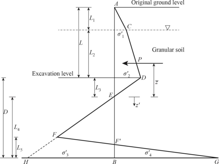
Refer Figure (1),
Find the depth of water table level
Find the rankine active pressure coefficient
Find the rankine passive pressure coefficient
Find the difference between the rankine active pressure coefficient and rankine passive pressure coefficient:
Find the effective unit weight of sand
At the water table level:
Find the intensity of the active pressure to the right of the pile
At the excavation level:
Find the intensity of the active pressure to the right of the pile
Find the depth below the dredge line
Find the area of the pressure diagram (P):
Find the area of the pressure diagram into center of pressure
Find the center of pressure to the area
Find the intensity of the passive pressure
Find the area
Find the area
Find the area
Find the area
Find the depth below point E
Use trial and error method to calculate depth below point E
Try
Substitute 4.30 m for
Hence, the assumption is correct.
The depth below point E is 4.30 m.
Find the depth below the dredge line to bottom of the pile (D):
Increase the depth below the dredge line to bottom of the pile by 30%. The depth below the dredge line to bottom of the pile (D) is 6.214 m.
Find required actual depth of the sheet pile
Thus, the required actual depth of the sheet pile is
Want to see more full solutions like this?
Chapter 18 Solutions
Principles Of Foundation Engineering 9e


- A 5 m wide braced excavation is made in a saturated clay, as shown in Figure P19.1, with the following properties: c = 20 kN/m2, = 0, and = 18.5 kN/m3. The struts are spaced at 5 m center to center in plan. a. Determine the strut forces. b. Determine the section modulus of the sheet pile required, assuming all = 170 MN/m2. c. Determine the maximum moment for the wales at levels B and C.arrow_forwardFor the braced cut described in Problem 15.16, assume that all = 170 MN/m2. a. Determine the sheet pile section (section modulus) b. What is the section modulus of the wales at level A? 15.16 Refer to the braced cut in Figure 15.50, for which = 17 kN/m3, = 30, and c = 0. The struts are located at 3 m on center in the plan. Draw the earth pressure envelope and determine the strut loads at levels A, B, and C. FIG. 15.50arrow_forwardThe cross section of a braced cut supporting a sheet pile installation in a clay soil is shown in Figure 14.22. Given: H = 12 m, clay = 17.9 kN/m3, = 0, c = 75 kN/m2, and the center-to-center spacing of struts in plan view, s = 3 m. a. Using Pecks empirical pressure diagrams, draw the earth-pressure envelope. b. Determine the strut loads at levels A, B, and C.arrow_forward
- In Problem 18.4, find the maximum bending moment in the sheet pile and determine the required section modulus, assuming an allowable stress of 190 MN/m2. 18.4 Refer to Figure 18.13. Given L1 = 1.5 m, L2 = 3 m; for the sand, =33, =16.5kN/m3, sat=19.0kN/m3; and, for the clay, c=50kN/m2, =0, sat=20kN/m3. Determine the depth of sheet pile required, allowing for a 50% increase from the theoretical estimate.arrow_forwardDetermine (a) the lateral earth pressure distribution for the braced cut analysis (including shape and value of earth pressure), (b) the strut loads for the horizontal supports of the braced cut. The lateral spacing, S,between the struts is 3 m. (c) Determine the factor of safety against bottom heave, if the length and width of the excavation are 20 m and 15 m,respectively, and the depth of the bottom of the excavation to the gravel layer is 6 m.arrow_forwardThe cross section of a braced cut supporting a sheet pile installation in a clay soil is shown in the figure below. Given: H = 12 m , clay = 17.9 kN/m3 , = 0 , C = 75 kN/m2 , and the center-to-center spacing of struts in plan view , S = 3 m.arrow_forward
- A 4-m high embankment is to be constructed as shown in the Fig. 3 below. If the unit weight of soil used in the embankment is 19.0 kN/m3, calculate the vertical stress due to the embankment loading at points P1, P2 and P3. Use the Straight Line Law of Osterberg, 1957.arrow_forwardThe water table at a site is at 5 m below the ground level, and it is required to excavate to this level. The soil profile consists of a thick bed of sand where the unit weight is m = 17.0 kN/m3 above the water table and sat = 20.0 kN/m3 below the water table. The friction angle of the sand is 37. The wall of the excavation will be supported by cantilever sheet piles. How deep would you drive the sheet piles? Use the simplified analysis (Figure 15.37) with a factor of safety of 1.5 on the passive resistance. Determine the maximum bending moment in the sheet pile and the required section modulus for the sheet pile section (given an allowable stress of 190 MN/m2).arrow_forwardA damn having a triangular section has a vertical face 24 m high and base 12 m wide. Use sg=2.4 a. determine the height of water that could rise on the vertical side of the dam so that the maximum intensity of pressure at the toe is twice the average pressure at the base. Neglect hydrostatic uplift. b. What is the shearing stress at the base?arrow_forward
- Refer to Figure 18.26b. Let L = 15.24 m, fill = 17.29 kN/m3, sat(clay) = 19.49 kN/m3, clay = 20, Hf = 3.05 m, and D = 0.406 m. The water table coincides with the top of the clay layer. Determine the total downward drag on the pile. Assume that = 0.6 clay. FIG. 18.26 Negative skin frictionarrow_forwardFigure 2 shows the cross-section of a 7m-wide, 2.5m-deep excavation that will be used to build a large sewer line. The excavation is supported by sheet pile walls that extend through layers of sand layers. The friction angle of the sand 1 and sand 2 is 30° and 35°, respectively. Explain your assumptions. Draw the earth pressure diagrams (some of the earth pressures will be function of “d”, embedment depth). Find the embedment depth “d” using the simplified method. Find the maximum moment on the wall and minimum section modulus required.arrow_forward
 Principles of Foundation Engineering (MindTap Cou...Civil EngineeringISBN:9781337705028Author:Braja M. Das, Nagaratnam SivakuganPublisher:Cengage Learning
 Fundamentals of Geotechnical Engineering (MindTap...Civil EngineeringISBN:9781305635180Author:Braja M. Das, Nagaratnam SivakuganPublisher:Cengage Learning
 Principles of Foundation Engineering (MindTap Cou...Civil EngineeringISBN:9781305081550Author:Braja M. DasPublisher:Cengage Learning
 Principles of Geotechnical Engineering (MindTap C...Civil EngineeringISBN:9781305970939Author:Braja M. Das, Khaled SobhanPublisher:Cengage Learning