
Applied Statics and Strength of Materials (6th Edition)
6th Edition
ISBN: 9780133840544
Author: George F. Limbrunner, Craig D'Allaird, Leonard Spiegel
Publisher: PEARSON
expand_more
expand_more
format_list_bulleted
Videos
Textbook Question
Chapter 19, Problem 19.15SP
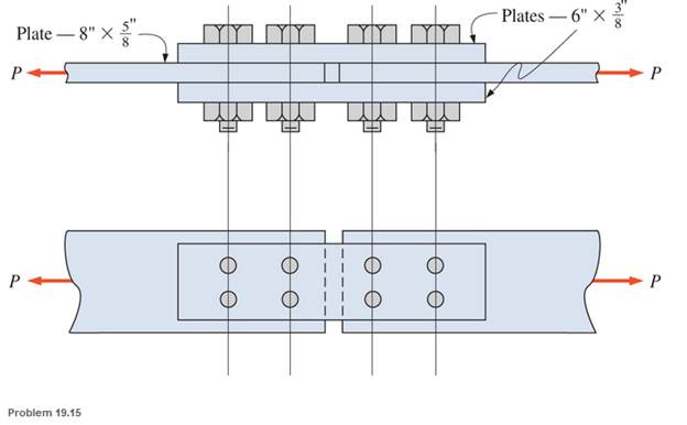
Calculate the allowable tensile load for the butt joint shown. The fasteners are
Expert Solution & Answer
Want to see the full answer?
Check out a sample textbook solution
Students have asked these similar questions
Two 1/4 in × 8 in A36 steel plates are joined with a lap joint using 3/4 in A325-N bolts. If a concentric unfactored live load of 50 kips (dead load = 0) is required to be resisted by the connection and the bolt shear strength controls the design, the minimum required number of bolts is?
Design a single riveted lap joint to connect two mild steel plates, 14.5 mm thick, the joint being designed for maximum efficiency. The allowable stresses are σt = 55 N/mm2 , = 32.5 N/mm2 and σc = 63.5 N/mm2 . Also calculate the minimum force per pitch which will rupture the joint
1/2-inch thick steel bar is welded to the vertical supportA) Calculate the allowable load if the electrode is E7018, the bar is 1015 cold drawn steel, the support is 1020 cold drawn steel.
Chapter 19 Solutions
Applied Statics and Strength of Materials (6th Edition)
Ch. 19 - Prob. 19.1PCh. 19 - Rework Problem 19.1 assuming a bearing-type...Ch. 19 - Rework Problem 19.1 assuming a bearing-type...Ch. 19 - Compute the allowable tensile load for the...Ch. 19 - Rework Problem 19.4 assuming a bearing-type...Ch. 19 - Rework Problem 19.4 assuming that the bolts are 34...Ch. 19 - Select the number and arrangement of 34 in....Ch. 19 - Calculate the allowable tensile load for the...Ch. 19 - In the connection shown, 14 in. side and end...Ch. 19 - Design the fillet welds parallel to the applied...
Ch. 19 - A fillet weld between two steel plates...Ch. 19 - Design an end connection using longitudinal welds...Ch. 19 - Calculate the allowable tensile load for the butt...Ch. 19 - Calculate the allowable tensile load for the lap...Ch. 19 - Calculate the allowable tensile load for the butt...Ch. 19 - Rework Problem 19.10 assuming that both plates are...Ch. 19 - Rework Problem 19.12 assuming that the angle is an...Ch. 19 - Two ASTM A36 steel plates, each 12 in. by 12 in. ,...Ch. 19 - Rework Problem 19.20 changing the fasteners to 34...Ch. 19 - Calculate the minimum main plate thickness for the...Ch. 19 - A roof truss tension member is made up of 2L6412...Ch. 19 - Rework Problem 19.23 changing the fasteners to six...Ch. 19 - Determine the allowable tensile load that can be...Ch. 19 - The welded connection shown is subjected to an...Ch. 19 - In Problem 19.26, use a 38 in. fillet weld, change...
Knowledge Booster


Learn more about
Need a deep-dive on the concept behind this application? Look no further. Learn more about this topic, mechanical-engineering and related others by exploring similar questions and additional content below.Similar questions
- Determine the safe tensile load for bolts of (a) M 17 and (b) M 26. Assume that the bolts are not initially stressed and take the safe tensile stress as 305 MPaarrow_forwardDetermine the safe tensile load for bolts of (a)M 17and (b) M 26. Assume that the bolts are not initially stressed and take the safe tensile stress as 305MPa.arrow_forwardCalculate external support reactions, and the forces on the internal joints.arrow_forward
- For the lap connection shown, the rivets are 19-mm diameter and the plates are 8 mm thick. The rivets used are A502, Grade 1 and the plates are ASTM A36 with Fu = 400 MPa. Determine the value of Pin all possible modes of failure and the safe value of P that the connection can resist. Fv = 120 MPa, Fp = 1.2 Fu. Add 1.6 mm for the hole diameter. Ans. 297.6 KNarrow_forwardQuestion 01: Draw and label any screw thread and a fastener separately. Also, discuss the types of stresses acting on screw threads and fasteners.arrow_forwardA light standard for a highway is shown in figure 6.52. Although it is made entirely of welded aluminum, the member ABC is presumed to be continuous and pin connected at B and C. According to this conservative assumption, what is the tension force in the strut at B? Neglect the weight of the aluminum members.arrow_forward
- Use LRFD and design a 13-foot-long tension member and its connection for a service dead load of 8 kips and a service live load of 24 kips. No slip of the connection is permitted. The connection will be to a 3⁄8-inch-thick gusset plate, as shown in Figure . Use a single angle for the tension member. Use Group A bolts and A572 Grade 50 steel for both the tension member and the gusset plate.arrow_forwardIn a bolted joint two members are connected with an axial tightening force of 2200 N. If the bolt used has metric threads of 4 mm pitch, the torque required for achieving the tightening force isarrow_forwardWhat is the factor of safety when a 0.50-in, 6 x 19 medium plow steel wire rope carrying an 8800 lb load is bent around a 25-in sheave if the breaking strength of the rope is 8.5 tons?arrow_forward
- A cylinder head stud has a diameter of 14mm at the bottom of the thread. If the maximum tensile stress allowed in the material is 30MPa. Calculate the safe load the stud can carry.arrow_forwardDetermine the safe tensile load for fine series bolts of (a) M 24and (b) M 38. Assume that the bolts are not initially stressed and take the safe tensile stress as 450MPa.arrow_forwardA storage tank of air, 40 inches in diameter, is to with stand an internal pressure of 250 psi with a design factor of 3.5 based on Su. The steel has the strength equivalent of C1020 annealed with Su of 57 ksi, and the welded joints have a relative strength efficiency of 95%. Compute the ff: Tensile stress Plate thickness Stress on diametral section Longitudinal stressarrow_forward
arrow_back_ios
SEE MORE QUESTIONS
arrow_forward_ios
Recommended textbooks for you
 Welding: Principles and Applications (MindTap Cou...Mechanical EngineeringISBN:9781305494695Author:Larry JeffusPublisher:Cengage Learning
Welding: Principles and Applications (MindTap Cou...
Mechanical Engineering
ISBN:9781305494695
Author:Larry Jeffus
Publisher:Cengage Learning
Differences between Temporary Joining and Permanent Joining.; Author: Academic Gain Tutorials;https://www.youtube.com/watch?v=PTr8QZhgXyg;License: Standard Youtube License