
Applied Statics and Strength of Materials (6th Edition)
6th Edition
ISBN: 9780133840544
Author: George F. Limbrunner, Craig D'Allaird, Leonard Spiegel
Publisher: PEARSON
expand_more
expand_more
format_list_bulleted
Concept explainers
Videos
Textbook Question
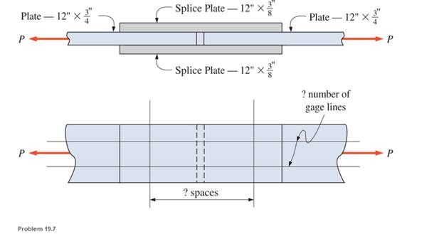
Chapter 19, Problem 19.7P
Select the number and arrangement of
Expert Solution & Answer
Want to see the full answer?
Check out a sample textbook solution
Students have asked these similar questions
Determine the safe tensile load for bolts of
(a)M 17and
(b) M 26. Assume that the bolts are not initially stressed and take the safe tensile stress as 305MPa.
Determine the safe tensile load for fine series bolts of (a) M 24and (b) M 38. Assume that the bolts are not initially stressed and take the safe tensile stress as 450MPa.
In the figure, the footbridge connection piece is connected to the steel column with the help of 3 bolts. It is desired that the 27 kN load be supported by the bolted connection with a safety factor of 2.3. Calculate the smallest bolt diameter accordingly. (Sut Bolt = 600 MPa)
Chapter 19 Solutions
Applied Statics and Strength of Materials (6th Edition)
Ch. 19 - Prob. 19.1PCh. 19 - Rework Problem 19.1 assuming a bearing-type...Ch. 19 - Rework Problem 19.1 assuming a bearing-type...Ch. 19 - Compute the allowable tensile load for the...Ch. 19 - Rework Problem 19.4 assuming a bearing-type...Ch. 19 - Rework Problem 19.4 assuming that the bolts are 34...Ch. 19 - Select the number and arrangement of 34 in....Ch. 19 - Calculate the allowable tensile load for the...Ch. 19 - In the connection shown, 14 in. side and end...Ch. 19 - Design the fillet welds parallel to the applied...
Ch. 19 - A fillet weld between two steel plates...Ch. 19 - Design an end connection using longitudinal welds...Ch. 19 - Calculate the allowable tensile load for the butt...Ch. 19 - Calculate the allowable tensile load for the lap...Ch. 19 - Calculate the allowable tensile load for the butt...Ch. 19 - Rework Problem 19.10 assuming that both plates are...Ch. 19 - Rework Problem 19.12 assuming that the angle is an...Ch. 19 - Two ASTM A36 steel plates, each 12 in. by 12 in. ,...Ch. 19 - Rework Problem 19.20 changing the fasteners to 34...Ch. 19 - Calculate the minimum main plate thickness for the...Ch. 19 - A roof truss tension member is made up of 2L6412...Ch. 19 - Rework Problem 19.23 changing the fasteners to six...Ch. 19 - Determine the allowable tensile load that can be...Ch. 19 - The welded connection shown is subjected to an...Ch. 19 - In Problem 19.26, use a 38 in. fillet weld, change...
Knowledge Booster


Learn more about
Need a deep-dive on the concept behind this application? Look no further. Learn more about this topic, mechanical-engineering and related others by exploring similar questions and additional content below.Similar questions
- An aluminum rod, made from alloy 6061-T6, is made in the form of a hollow square tube, 2.25 in outside with a wall thickness of 0.125 in. Its length is 16.0 in. It carries an axial compressive force of 12 600 lb. Compute the resulting design factor. Assume that the tube does not buckle.arrow_forwardDraw FBD and determine Stress and Safety Factor of Bicycle Axle (Thru Axel) Specification Weight of cyclist = 120 kg. Materials: Aluminum alloy (AL 6061-T6) Dimension: Length = 122 mm, Diameter = 12 mm, Thread pitch = 1.75 mm, Thread Length = 16 mm.arrow_forwardUse LRFD and design a 13-foot-long tension member and its connection for a service dead load of 8 kips and a service live load of 24 kips. No slip of the connection is permitted. The connection will be to a 3⁄8-inch-thick gusset plate, as shown in Figure . Use a single angle for the tension member. Use Group A bolts and A572 Grade 50 steel for both the tension member and the gusset plate.arrow_forward
- Which of the following is the design stress for a piston rod where the axial load is completely reversed if the surface of the rod is ground and the surface finish factor is 0.9? Assume no stress concentration. Use a factor of safety of 2 and an endurance limit of 250 MPa. The load factor for completely reversed axial load is 0.85.arrow_forward10.20: Design a 3-m- long rod subjected to a tensile load of 67.5 kN. Using a factor of safety of 2.5 based on the yield stress, calculate the required rod diameter if it is to be made of (a) steel with a yield stress of 310 MPa. (b) aluminum alloy with a yield stress of 240 MPa.arrow_forwardA rigid coupling with 30 inches of bolt circle diameter transmits a torque of 18,000 lb-in. The coupling material has a yield strength of 90,000 psi. The coupling is fastened by six bolts. Assume design factor of N=3 Calculate the diameter of each bolt.arrow_forward
- For a rod made of aluminum alloy 2014-T6, select the smallest square cross section that can be used if the rod is to carry a 55-kip centric load.arrow_forwardDiscuss what is meant by buckling for a long slender bar. Discuss the difference of a pin supported column in comparison to a fixed supported column. Support your answer with appropriate sketches.arrow_forward(a) Explain FIVE (5) factors that may influence the optimum column design under an axial compressive load. (b) A 3.6 m long pin-ended column is formed from an A-36 steel circular hollow section with an outer diameter of 75 mm. Determine the minimum thickness, t (to the nearest integer in mm) of the circular hollow section so that the column can safely support the load of 200 kN without buckling. If the outer diameter of the steel circular hollow section is reduced to 62 mm and the ends are pinned-fixed supported, analyse whether the column with the same applied load and the sectional thickness computed above will cause a buckling failure.arrow_forward
- Select the lightest WT4 shape to be used as a 20 ft long tension member to resist the of dead load, D=40 k, live load, L=60 k, snow load, PS=25 k, and earthquake, E=110 k. The connection is two lines of bolts through the flange with three 3/4-in ∅ bolts in each line spaced at 3 in on center. Use A992 Grade 50 steel. Neglect block shear.arrow_forward1.1.7.5 Hint: Determined as the lowest load considering all of the allowable compressive load of spar, shear stress of pin, and pressure stress of pin and connecting plate.arrow_forwardA circular-cross-section bar with a diameter of 50mm and a length of 1.25 m is axially loaded. The baris made of medium-carbon steel. Both ends are pinned.Determine(a) Whether the Johnson or the Euler formula shouldbe used.(b) The critical load.arrow_forward
arrow_back_ios
SEE MORE QUESTIONS
arrow_forward_ios
Recommended textbooks for you
 Elements Of ElectromagneticsMechanical EngineeringISBN:9780190698614Author:Sadiku, Matthew N. O.Publisher:Oxford University Press
 Mechanics of Materials (10th Edition)Mechanical EngineeringISBN:9780134319650Author:Russell C. HibbelerPublisher:PEARSON
 Thermodynamics: An Engineering ApproachMechanical EngineeringISBN:9781259822674Author:Yunus A. Cengel Dr., Michael A. BolesPublisher:McGraw-Hill Education
 Control Systems EngineeringMechanical EngineeringISBN:9781118170519Author:Norman S. NisePublisher:WILEY
 Mechanics of Materials (MindTap Course List)Mechanical EngineeringISBN:9781337093347Author:Barry J. Goodno, James M. GerePublisher:Cengage Learning
 Engineering Mechanics: StaticsMechanical EngineeringISBN:9781118807330Author:James L. Meriam, L. G. Kraige, J. N. BoltonPublisher:WILEY
Elements Of Electromagnetics
Mechanical Engineering
ISBN:9780190698614
Author:Sadiku, Matthew N. O.
Publisher:Oxford University Press
Mechanics of Materials (10th Edition)
Mechanical Engineering
ISBN:9780134319650
Author:Russell C. Hibbeler
Publisher:PEARSON
Thermodynamics: An Engineering Approach
Mechanical Engineering
ISBN:9781259822674
Author:Yunus A. Cengel Dr., Michael A. Boles
Publisher:McGraw-Hill Education
Control Systems Engineering
Mechanical Engineering
ISBN:9781118170519
Author:Norman S. Nise
Publisher:WILEY
Mechanics of Materials (MindTap Course List)
Mechanical Engineering
ISBN:9781337093347
Author:Barry J. Goodno, James M. Gere
Publisher:Cengage Learning
Engineering Mechanics: Statics
Mechanical Engineering
ISBN:9781118807330
Author:James L. Meriam, L. G. Kraige, J. N. Bolton
Publisher:WILEY
EVERYTHING on Axial Loading Normal Stress in 10 MINUTES - Mechanics of Materials; Author: Less Boring Lectures;https://www.youtube.com/watch?v=jQ-fNqZWrNg;License: Standard YouTube License, CC-BY