
Calculate the voltage gain, current gain, input impedance, and output impedance for the amplifier shown in Figure 19.131 in the textbook.
Answer to Problem 92P
The voltage gain, current gain, input impedance, and output impedance for the amplifier are
Explanation of Solution
Given Data:
Refer to Figure 19.131 in the textbook for the amplifier circuit.
From the given amplifier circuit, the internal resistance
Formula used:
Refer to Equation 19.73 in the textbook and write the expression for voltage gain of a amplifier in terms of hybrid parameters as follows:
Here,
Write the expression for current gain of the amplifier as follows:
Here,
Write the expression for input impedance of the amplifier as follows:
Calculation:
Redraw the given circuit as shown in Figure 1.
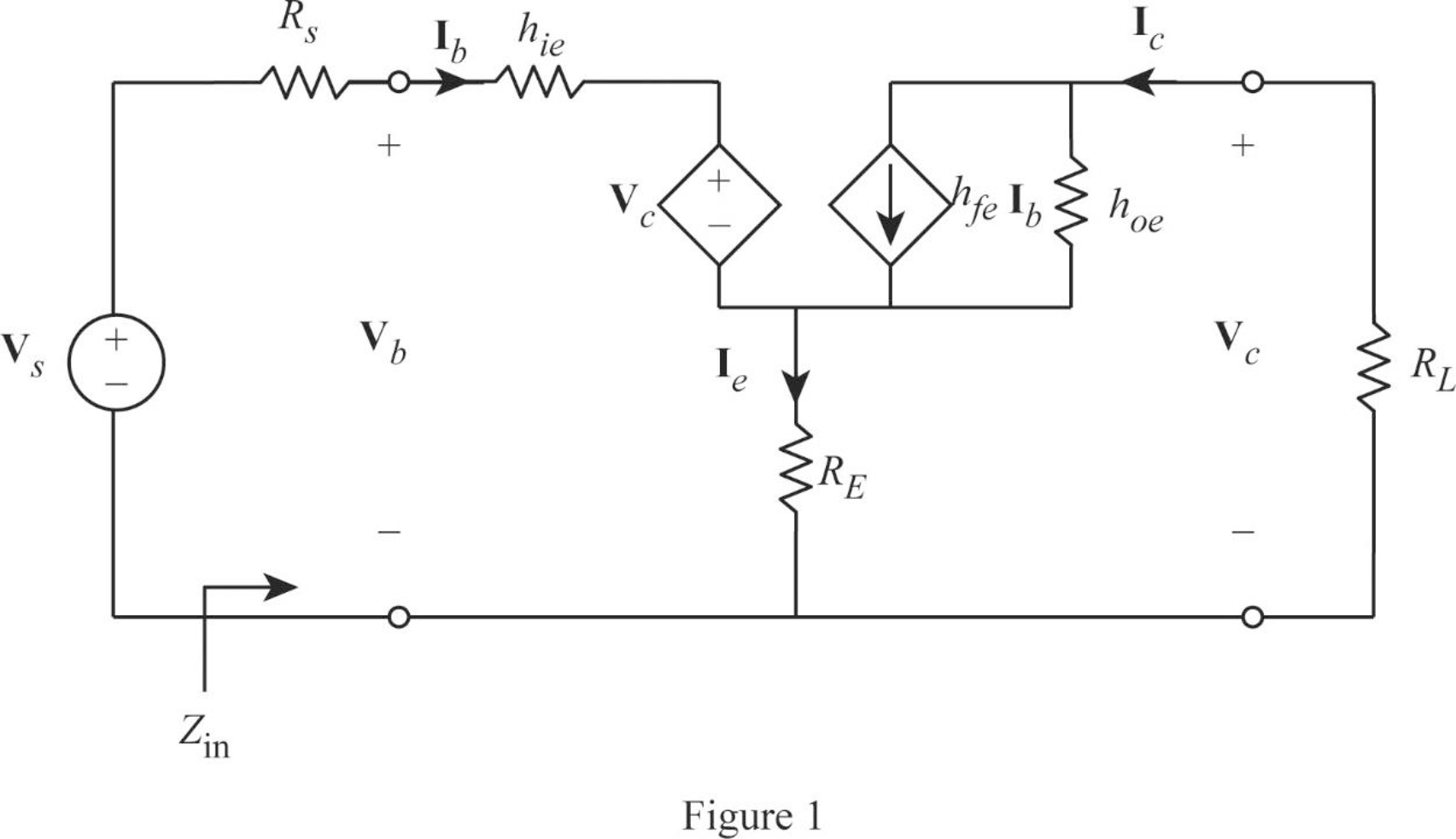
From Figure 1, write the expression for emitter current as follows:
Write the expression for base voltage from the circuit in Figure 1 as follows:
Write the expression for collector current as follows:
Write the expression for collector voltage as follows:
From Equation (7), substitute
Rearrange the expression as follows:
From Equation (2), substitute
Substitute 100 for
From Equation (6), substitute
Rearrange the expression as follows:
Rearrange the expression in Equation (5) as follows:
From Equations (7) and (9), substitute
Rearrange the expression as follows:
Substitute 100 for
Simplify the expression as follows:
From Equation (1), substitute
From Equation (9), substitute
Rearrange the expression as follows:
Substitute 100 for
From Equation (3), substitute
Consider output voltage
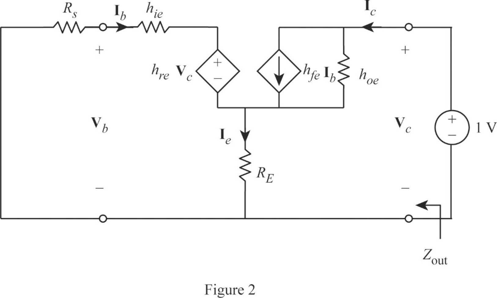
Apply KVL to the input loop for the circuit in Figure 2 as follows:
Substitute 1 for
Apply KCL at the output node for the circuit in Figure 2 as follows:
Substitute 1 for
Rearrange the expression as follows:
From Equation (12), substitute
Substitute 100 for
Write the expression for output impedance of the amplifier as follows:
Substitute 1 for
Conclusion:
Thus, the voltage gain, current gain, input impedance, and output impedance for the amplifier are
Want to see more full solutions like this?
Chapter 19 Solutions
EBK FUNDAMENTALS OF ELECTRIC CIRCUITS

- Circuit theoryarrow_forwardPlease Answer my question A,B 2 sub parts .... Because I know this team can answer max 3 sub parts... Please answer my question with the parts... Thank u god bless uarrow_forwardconsider the JFET circuit as shown in the fig. 1 the parameterrs IDSS= 4mA and Vp= -4V, calculate the output voltage, Vo if Vi= 0 and Input voltage , Vi if Vo= 0arrow_forward
- a) b) c) Draw the DC equivalent model and use it to find the quiescent operating parameters. Draw the AC equivalent model and use it to find Zin, Zout, Av, Ai, and G. Compare Av and Zo in this problem with that of the similar Problem 6. Comment on the results, and state what application each would be best suited for. R in RS w 1 ΚΩ +15 V +15 V ẞ = 100 C₁ R₁10 k ΚΩ VBE = 0.7 V Vin R₂ 10 ΚΩ RE W Copyright ©2018 Pearson Education, All Rights Reserved: C₂ し -O + 1 k vo RL WI - 500 Ωarrow_forwardCircuit Theory 2 Analysisarrow_forwardActivity Output 1. Find the total resistance at terminal A-B 36 56 13 А ww 47 13 46 43 93 43 B wwarrow_forward
- Q/ An a.c bridge is in balance with the following constants : Arm AB , R=200 Q in series with C= 0.265 µF. Arm AC , R,=300 2. Arm CD , Unknown. Arm BD, C3= 0.79 µF. The oscillator frequency is 1kHz , supply voltage =lvolt between A and D points. Find: Zx and calculate its components ( R, L or C).arrow_forwardID-19-41240-2arrow_forwardPlease be fast...arrow_forward
- N:02) Obtain the output voltage equation.arrow_forwardQ/ An a.c bridge is in balance with the following constants : Arm AB , R=200 2 in series with C= 0.265 µF Arm AC , R2=300 2. Arm CD , Unknown. Arm BD, C3= 0.79 uF. The oscillator frequency is 1kHz , supply voltage =1volt between A and D points. Find: Zx and calculate its components (R, L or C).arrow_forward1. If the input voltage 32VP.P and f=50HZ, sketch the output of the circuit shown below. TD D. 10k =3 V =4 V 2. Determine Vo 20 y Si I ka Preced IRAQI UNIVERSITYarrow_forward
 Introductory Circuit Analysis (13th Edition)Electrical EngineeringISBN:9780133923605Author:Robert L. BoylestadPublisher:PEARSON
 Delmar's Standard Textbook Of ElectricityElectrical EngineeringISBN:9781337900348Author:Stephen L. HermanPublisher:Cengage Learning
 Programmable Logic ControllersElectrical EngineeringISBN:9780073373843Author:Frank D. PetruzellaPublisher:McGraw-Hill Education
 Fundamentals of Electric CircuitsElectrical EngineeringISBN:9780078028229Author:Charles K Alexander, Matthew SadikuPublisher:McGraw-Hill Education
 Electric Circuits. (11th Edition)Electrical EngineeringISBN:9780134746968Author:James W. Nilsson, Susan RiedelPublisher:PEARSON
 Engineering ElectromagneticsElectrical EngineeringISBN:9780078028151Author:Hayt, William H. (william Hart), Jr, BUCK, John A.Publisher:Mcgraw-hill Education,