
Videos
Assume that the two circuits in Fig. 19.135 are equivalent. The parameters of the two circuits must be equal. Using this factor and the z parameters, derive Eqs. (9.67) and (9.68).
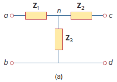
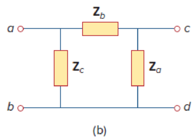
Figure 19.135
Derive the expressions in Equations (9.67) and (9.68) in the textbook.
Explanation of Solution
Given Data:
Refer to Figure 19.135 in the textbook given circuits.
Consider the parameters of two circuits are equal.
Calculation:
Refer to Figure 19.135 (a) in the textbook and write the expression for
Refer to Figure 19.135 (b) in the textbook and write the expression for
From Equation (1), substitute
Refer to Figure 19.135 (a) in the textbook and write the expression for
Refer to Figure 19.135 (b) in the textbook and write the expression for
From Equation (3), substitute
Refer to Figure 19.135 (a) in the textbook and write the expression for
Refer to Figure 19.135 (b) in the textbook and write the expression for
From Equation (5), substitute
Subtract Equation (4) from Equation (2) and obtain the expression as follows:
Add Equations (6) and (7) and obtain the expression as follows:
Simplify the expression as follows:
Subtract Equation (8) from Equation (6) and obtain the expression as follows:
Subtract Equation (8) from Equation (2) and obtain the expression as follows:
From Equations (8), (9), and (10), the expressions in Equation (9.68) are derived.
Note that, the obtained expressions are not same as the expressions in the textbook, since the position of the impedances are changed in the given circuits.
Use expressions in Equations (8), (9), and (10) and obtain the expression as follows:
Divide Equation (11) by Equation (8) and obtain the expression as follows:
Divide Equation (11) by Equation (9) and obtain the expression as follows:
Divide Equation (11) by Equation (10) and obtain the expression as follows:
From Equations (12), (13), and (14), the expressions in Equation (9.67) are derived.
Note that, the obtained expressions are not same as the expressions in the textbook, since the position of the impedances are changed in the given circuits.
Conclusion:
Thus, the expressions in Equations (9.67) and (9.68) in the textbook are derived.
Want to see more full solutions like this?
Chapter 19 Solutions
EBK FUNDAMENTALS OF ELECTRIC CIRCUITS


- Y parameterarrow_forwardIf a 50 mV r.m.s. input signal is applied to the amplifier in Fig. 19.68, what is the peak-to-peak output voltage? Given that g„= 5000 µs. [920 mV] VDD + 12 V 1.5 kn R, C3 v out 10µF VinoHE 10 μF R,=10 k2 C2 I µF 10 M2 RG 1 kN ZRs Fig. 19.68arrow_forwardfind the z-parametersarrow_forward
- Find The Impedance At The Input Port of the circuit in Fig. 19.27arrow_forward12 Prob.19. Find – (i) Z-parameters (ü) Y-parameters. 5 2 22 V 1 V 2 5 Varrow_forwardPractice Problem 19.6 Find the impedance at the input port of the cicuit in Fig. 19.27. Answer: 1.6667 kfl. b =2 ka = 10 b = 100 = 10s 30 ka Figure 19.27 For Practice Prob. 19.6.arrow_forward
- Nonearrow_forward10 For he circuit shown in the figure below, find Z- * ?Parameters 100 80 120 V1 160 V2 21.21 ohm, 19.19 ohm, 23.86 ohm 21.19 ohm, 19.86 ohm, 23.21 ohm O 21.86 ohm, 19.19 ohm, 23.21 ohm O 21.86 ohm, 19.21 ohm, 23.19 ohm Oarrow_forwarda) b) c) Draw the DC equivalent model and use it to find the quiescent operating parameters. Draw the AC equivalent model and use it to find Zin, Zout, Av, Ai, and G. Compare Av and Zo in this problem with that of the similar Problem 6. Comment on the results, and state what application each would be best suited for. R in RS w 1 ΚΩ +15 V +15 V ẞ = 100 C₁ R₁10 k ΚΩ VBE = 0.7 V Vin R₂ 10 ΚΩ RE W Copyright ©2018 Pearson Education, All Rights Reserved: C₂ し -O + 1 k vo RL WI - 500 Ωarrow_forward
- Practice Problem 19.6 h = 2 kΩ h12 = 104 h₂1 = 100 h22 = 10-5 S Zin Figure 19.27 For Practice Prob. 19.6. www 50 ΚΩ Find the impedance at the input port of the circuit in Fig. 19.27. Answer: 1.6667 kN.arrow_forwardDO NOT COPY FROM OTHER WEBSITES Correct and detailed answer will be Upvoted else downvoted. Thank you!arrow_forwardI need the answer as soon as possiblearrow_forward
 Introductory Circuit Analysis (13th Edition)Electrical EngineeringISBN:9780133923605Author:Robert L. BoylestadPublisher:PEARSON
 Delmar's Standard Textbook Of ElectricityElectrical EngineeringISBN:9781337900348Author:Stephen L. HermanPublisher:Cengage Learning
 Programmable Logic ControllersElectrical EngineeringISBN:9780073373843Author:Frank D. PetruzellaPublisher:McGraw-Hill Education
 Fundamentals of Electric CircuitsElectrical EngineeringISBN:9780078028229Author:Charles K Alexander, Matthew SadikuPublisher:McGraw-Hill Education
 Electric Circuits. (11th Edition)Electrical EngineeringISBN:9780134746968Author:James W. Nilsson, Susan RiedelPublisher:PEARSON
 Engineering ElectromagneticsElectrical EngineeringISBN:9780078028151Author:Hayt, William H. (william Hart), Jr, BUCK, John A.Publisher:Mcgraw-hill Education,