
Bundle: Mechanics Of Materials, Loose-leaf Version, 9th + Mindtap Engineering, 1 Term (6 Months) Printed Access Card
9th Edition
ISBN: 9781337594318
Author: Barry J. Goodno; James M. Gere
Publisher: Cengage Learning
expand_more
expand_more
format_list_bulleted
Videos
Textbook Question
thumb_up100%
Chapter 2, Problem 2.2.11P
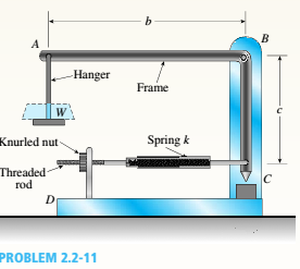
A small lab scale has a rigid L-shaped frame ABC consisting of a horizontal arm AB (length b = 10 in.) and a vertical arm BC (length c = 7 in.) pivoted al point B. The pivot is attached to the outer frame BCD that stands on a laboratory bench.
The position of the pointer al C is controlled by a spring, Jt = 5 lb/in., that is attached to a threaded rod. The pitch of the threads is p = 1/16 in. Under application of load W, 12 revolutions of the nut are required to bring the pointer back to the mark. Calculate the weight W.
Expert Solution & Answer

Trending nowThis is a popular solution!

Students have asked these similar questions
Prob. # 1] Figure below shows a crank loaded by a force F = 300 lb that causes twisting and
bending of a 3/4-inch-diameter shaft fixed to a support at the origin of the reference system. In
actuality, the support may be an inertia, but for the purposes of a stress analysis consider this
as a statics problem.
a) Draw separate free-body diagrams of the shaft AB and the arm BC, and compute the
values of all forces, moments, and torques. Label the directions of the coordinate axes
on these diagrams.
b) Compute the torsional stress and the bending stress in the arm BC and indicate where
these act.
c) Locate a stress element on the top surface of the shaft at A, and calculate all the stress
components that act upon this element.
d) Determine the maximum and minimum principal stresses at point A, and the angle of
inclination of the planes on which the principal stresses act.
e) Determine maximum shear stress at point A and the angle of inclination of the element
on which the maximum shear…
Problem 2.
A uniform bar of mass m is pivoted at point O and supported at the ends by two springs, as shown in
Figure 2. End P of spring PQ is subjected to a sinusoidal displacement, x(t) = x,sinwt.
1=1 m, k=1000 N/m, m=10 kg, xo=1 cm, and w=10 rad/s.
a) Drive the equations of motion and find the natural frequency of the bar
b) Find the steady-state angular displacement of the bar
Simulate the system and plot displacements for the following cases (choose suitable simulation
Vont
time for each case):
1) With the initial conditions theta0=thetad0=0, an excitation xEsin(wi) Is applied vertically
at point P. Choose such w values so that the system is
i. in resonance,
exPeriencing beating.
do
D
ii.
(1) = xo sin wt
Uniform bar,
mass m
31
Figure 2. Spring-mass system
Problem 2.
A uniform bar of mass m is pivoted at point O and supported at the ends by two springs, as shown in
Figure 2. End P of spring PQ is subjected to a sinusoidal displacement, x(t) = x,sinwt.
1=1 m, k=1000 N/m, m=10 kg, xo=1 cm, and w=10 rad/s.
a) Drive the equations of motion and find the natural frequency of the bar
b) Find the steady-state angular displacement of the bar
Vont
do
Simulate the system and plot displacements for the following cases (choose suitable simulation
time for each case):
1) With the initial conditions theta0=thetad0=0, an excitation x=xesin(wt) is applied vertically
at point P. Choose such w values so that the system is
in resonancer
experiencing beating.
i.
D
ii.
xt t) = xo sin wt
Uniform bar,
k
mass m
Figure 2. Spring-mass system
Chapter 2 Solutions
Bundle: Mechanics Of Materials, Loose-leaf Version, 9th + Mindtap Engineering, 1 Term (6 Months) Printed Access Card
Ch. 2 - A 10-ft rigid bar AB is supported with a vertical...Ch. 2 - Rigid bar ABC is supported with a pin at A and an...Ch. 2 - The L-shaped arm ABCD shown in the figure lies in...Ch. 2 - A steel cable with a nominal diameter of 25 mm...Ch. 2 - A steel wire- and an aluminum allay wire have...Ch. 2 - By what distance h does the cage shown in the...Ch. 2 - Rigid bar ACB is supported by an elastic circular...Ch. 2 - A plastic cylinder is held snugly between a rigid...Ch. 2 - A safety valve on the top of a tank containing...Ch. 2 - The device shown in the figure consists of a...
Ch. 2 - A small lab scale has a rigid L-shaped frame ABC...Ch. 2 - A small lab scale has a rigid L-shaped frame ABC...Ch. 2 - Two rigid bars are connected to each other by two...Ch. 2 - The three-bar truss ABC shown in the figure part a...Ch. 2 - An aluminum wire having a diameter d = 1/10 in....Ch. 2 - A uniform bar AB of weight W = 25 N is supported...Ch. 2 - A hollow, circular, cast-iron pipe (Ec =12,000...Ch. 2 - The horizon Lai rigid beam A BCD is supported by...Ch. 2 - Two pipe columns (AB, FC) are pin-connected to a...Ch. 2 - A framework ABC consists of two rigid bars AB and...Ch. 2 - Solve the preceding problem for the following...Ch. 2 - The length of the end segments of the bar (see...Ch. 2 - A long, rectangular copper bar under a tensile...Ch. 2 - An aluminum bar AD (see figure) has a...Ch. 2 - A vertical bar consists of three prismatic...Ch. 2 - A vertical bar is loaded with axial loads at...Ch. 2 - Repeat Problem 2.3-4, but now include the weight...Ch. 2 - -7 Repeat Problem 2.3-5, but n include the weight...Ch. 2 - A rectangular bar of length L has a slot in the...Ch. 2 - Solve the preceding problem if the axial stress in...Ch. 2 - A two-story building has steel columns AB in the...Ch. 2 - A steel bar is 8.0 Ft long and has a circular...Ch. 2 - A bar ABC of length L consists of two parts of...Ch. 2 - A woodpile, driven into the earth, supports a load...Ch. 2 - Consider the copper lubes joined in the strength...Ch. 2 - The nonprismalic cantilever circular bar shown has...Ch. 2 - *16 A prismatic bar AB of length L,...Ch. 2 - A flat bar of rectangular cross section, length L,...Ch. 2 - A flat brass bar has length L, constant thickness...Ch. 2 - Repeat Problem 2.3-18, but assume that the bar is...Ch. 2 - Repeat Problem 2.3-18, but assume that the bar is...Ch. 2 - A slightly tapered bar AB of solid circular crass...Ch. 2 - A circular aluminum alloy bar of length L = 1.8 m...Ch. 2 - A long, slender bar in the shape of a right...Ch. 2 - A post AB supporting equipment in a laboratory is...Ch. 2 - The main cables of a suspension bridge (see figure...Ch. 2 - A uniformly tapered lube AB of circular cross...Ch. 2 - A vertical steel bar ABC is pin-supported at its...Ch. 2 - A T-frame structure is torn posed of a prismatic...Ch. 2 - A T-frame structure is composed of prismatic beam...Ch. 2 - Repeat Problem 2.3-29 if vertical load P at D is...Ch. 2 - A bar ABC revolves in a horizontal plane about a...Ch. 2 - The assembly shown in the figure consists of a...Ch. 2 - A cylindrical assembly consisting of a brass core...Ch. 2 - A steel bar with a uniform cross section, is fixed...Ch. 2 - A horizontal rigid bar ABC is pinned at end A and...Ch. 2 - A solid circular steel cylinder S is encased in a...Ch. 2 - Three prismatic bars, two of material A and one of...Ch. 2 - A circular bar ACB of a diameter d having a...Ch. 2 - Bar ABC is fixed at both ends (see figure) and has...Ch. 2 - Repeat Problem 2.4-8, but assume that the bar is...Ch. 2 - A plastic rod AB of length L = 0.5 m has a...Ch. 2 - 2.4-11 Three steel cables jointly support a load...Ch. 2 - The fixed-end bar ABCD consists of three prismatic...Ch. 2 - A lube structure is acted on by loads at B and D,...Ch. 2 - A hollow circular pipe (see figure} support s a...Ch. 2 - The aluminum and steel pipes shown in the figure...Ch. 2 - A rigid bar of weight W = SOO N hangs from three...Ch. 2 - A bimetallic bar (or composite bar) of square...Ch. 2 - S Three-bar truss ABC (see figure) is constructed...Ch. 2 - A horizontal rigid bar of weight If' = 72001b is...Ch. 2 - A rigid bar ABCD is pinned at point B and...Ch. 2 - A rigid bar AB if of a length B = 66 in. is....Ch. 2 - Find expressions For all support reaction forces...Ch. 2 - A trimetallic bar is uniformly compressed by an...Ch. 2 - Find expressions for all support reaction Forces...Ch. 2 - The rails of a railroad track are welded together...Ch. 2 - A circular steel rod of diameter d is subjected to...Ch. 2 - A rigid bar of weight W = 750 lb hangs from three...Ch. 2 - A steel rod. of 15-mm diameter is held snugly (but...Ch. 2 - A bar AB of length L is held between rigid...Ch. 2 - A beam is constructed using two angle sections (L...Ch. 2 - A W 8 × 28 beam of a length 10 ft is held between...Ch. 2 - A plastic bar ACB having two different solid...Ch. 2 - ,5-9 A flat aluminum alloy bar is fixed at both...Ch. 2 - Repeat Problem 2.5-9 for the flat bar shown in the...Ch. 2 - A circular steel rod AB? (diameter d, = 1.0 in.,...Ch. 2 - A circular, aluminum alloy bar of a length L = 1.8...Ch. 2 - Rectangular bars of copper and aluminum are held...Ch. 2 - A brass sleeve S is fitted over a steel bolt B...Ch. 2 - A rigid triangular frame is pivoted at C and held...Ch. 2 - ,5-16 A rigid bar ABCD is pinned at end A and...Ch. 2 - A copper bar AB with a length 25 in. and diameter...Ch. 2 - A steel wire AB is stretched between rigid...Ch. 2 - -19 The mechanical assembly shown in the figure...Ch. 2 - A bar AB having a length L and axial rigidity EA...Ch. 2 - Pipe 2 has been inserted snugly into Pipe I. but...Ch. 2 - A non prism elk- bar ABC made up of segments...Ch. 2 - Wires B and C are attached to a support at the...Ch. 2 - A rigid steel plate is supported by three posts of...Ch. 2 - A capped cast-iron pipe is compressed by a brass...Ch. 2 - A plastic cylinder is held snugly between a rigid...Ch. 2 - Prob. 2.5.27PCh. 2 - Consider the sleeve made From two copper tubes...Ch. 2 - A polyethylene tube (length L) has a cap that when...Ch. 2 - Prestressed concrete beams are sometimes...Ch. 2 - Prob. 2.5.31PCh. 2 - A steel bar of rectangular cross section (1.5 in....Ch. 2 - A circular steel rod of diameter d is subjected to...Ch. 2 - A standard brick (dimensions 8 in. × 4 in. × 2.5...Ch. 2 - A brass wire of diameter d = 2.42 mm is stretched...Ch. 2 - Prob. 2.6.5PCh. 2 - A steel bar with a diameter d = 12 mm is subjected...Ch. 2 - During a tension lest of a mild-steel specimen...Ch. 2 - A copper bar with a rectangular cross section is...Ch. 2 - A prismatic bar with a length L = 3 ft and...Ch. 2 - A prismatic bar with a length L = 1 m and...Ch. 2 - The plane truss in the figure is assembled From...Ch. 2 - Plastic bar of diameter d = 32 mm is compressed in...Ch. 2 - A plastic bar of rectangular cross section (ft =...Ch. 2 - A copper bar of rectangular cross section (b = 18...Ch. 2 - A circular brass bar with a diameter J is member...Ch. 2 - Two boards are joined by gluing along a scarf...Ch. 2 - Acting on the sides of a stress element cut from a...Ch. 2 - A prismatic bar is subjected to an axial force...Ch. 2 - The normal stress on plane pq of a prismatic bar...Ch. 2 - A tension member is to be constructed of two...Ch. 2 - -21 Plastic bar AB of rectangular cross section (6...Ch. 2 - A compression bar having a square cross section...Ch. 2 - A prismatic bar AD of length L, cross-sectional...Ch. 2 - A bar with a circular cross section having two...Ch. 2 - A three-story steel column in a building supports...Ch. 2 - The bar ABC shown in the figure is loaded by a...Ch. 2 - Determine the strain energy per unit volume (units...Ch. 2 - The truss ABC shown in the Figure is subjected to...Ch. 2 - -7 The truss A BC Shawn in the figure supports a...Ch. 2 - The statically indeterminate structure shown in...Ch. 2 - A slightly tapered bar AB of rectangular cross...Ch. 2 - A compressive load P is transmitted through a...Ch. 2 - A block B is pushed against three springs by a...Ch. 2 - A bungee cord that behaves linearly elastically...Ch. 2 - A sliding collar of weight W = 150 lb falls From a...Ch. 2 - Solve the preceding problem if the collar has mass...Ch. 2 - Prob. 2.8.3PCh. 2 - A block weighing W = 5.0 N drops inside a cylinder...Ch. 2 - Solve the preceding problem for W = 1.0 lb. h = 12...Ch. 2 - Prob. 2.8.6PCh. 2 - A weight W = 4500 lb falls from a height h onto a...Ch. 2 - Prob. 2.8.8PCh. 2 - Prob. 2.8.9PCh. 2 - A bumping post at the end of a track in a railway...Ch. 2 - A bumper for a mine car is constructed with a...Ch. 2 - A bungee jumper having a mass of 55 kg leaps from...Ch. 2 - Prob. 2.8.13PCh. 2 - A rigid bar AB having a mass M = 1.0 kg and length...Ch. 2 - The flat bars shown in parts a and b of the figure...Ch. 2 - The flat bars shown in parts a and b of the figure...Ch. 2 - A flat bar of width b and thickness t has a hole...Ch. 2 - Around brass bar of a diameter d1= 20mm has upset...Ch. 2 - Prob. 2.10.5PCh. 2 - ,10-6 A prismatic bar with a diameter d0= 20 mm is...Ch. 2 - A stepped bar with a hole (see figure) has widths...Ch. 2 - A bar AB of length L and weight density y hangs...Ch. 2 - A prismatic bar of length L = 1.8 m and...Ch. 2 - Prob. 2.11.3PCh. 2 - A prismatic bar in tension has a length L = 2.0 m...Ch. 2 - An aluminum bar subjected to tensile Forces P has...Ch. 2 - A rigid bar AB is pinned al end A and is supported...Ch. 2 - Two identical bars AB and BC support a vertical...Ch. 2 - A stepped bar ACB with circular cross sections is...Ch. 2 - A horizontal rigid bar AB supporting a load P is...Ch. 2 - Prob. 2.12.4PCh. 2 - The symmetric truss ABCDE shown in the figure is...Ch. 2 - Five bars, each having a diameter of 10 mm....Ch. 2 - Prob. 2.12.7PCh. 2 - A rigid bar ACB is supported on a fulcrum at C and...Ch. 2 - The structure shown in the figure consists of a...Ch. 2 - Two cables, each having a length i. of...Ch. 2 - A hollow circular tube T of a length L = 15 in. is...
Knowledge Booster


Learn more about
Need a deep-dive on the concept behind this application? Look no further. Learn more about this topic, mechanical-engineering and related others by exploring similar questions and additional content below.Similar questions
- A bumping post at the end of a track in a railway yard has a spring constant k = 8.0 MN/m (see figure). The maximum possible displacement d or the end of the striking plate is 450 mm. What is the maximum velocity vmaxthat a railway car of weight W = 545 kN can have without damaging the bumping post when it strikes it?arrow_forwardRepeat Problem 2.5-9 for the flat bar shown in the figure but assume that and thatarrow_forwardRepeat 1.3-9 but use the method of sections go find member forces in AC and BD.arrow_forward
- A bumper for a mine car is constructed with a spring of stiffness k = 1120 lb/in. (see figure). If a car weighing 3450 lb is traveling at velocity v = 7 mph when it strikes the spring, what is the maximum shortening of the spring?arrow_forwardThe inclined ladder AB supports a house painter (85 kg) at C and the weight iq = 40 K/m} of the ladder itself. Each ladder rail (t5= 4 mm) is supported by a shoe (ts= 5 mm) that is attached to the ladder rail by a bolt of diameter d = 8 mmarrow_forwardA helical spring is made of 10 m diameter steel wire wound on a 100 mm diameter mandrel. If there are 10 active coils what is spring constant Take: C= 100 GPA What force must be applied to the spring to elongate it by 50 mm?arrow_forward
- Member AB (helical spring) and Member AC (axial rod) are carrying a weight at point A. Member AB has the following properties: R = 90 mm, n -4 turns, G- 70 GPa, d- 30 mm, and Talow = 105 MPa while Member AC has the following properties: L= 2.A- 500 mm?, E = 200 GPa, and a low- 30 MPa. Determine the maximum safe %3D value of W (in N). Use simplified formula for the helical spring. A 60°arrow_forwardA crank shaft is operated as shown in the figure. A load F1 = 9.73 N is applied and the operator %3D dz applies a load P to counter. The system is in equilibrium and all of the bearings are perfectly dz aligned such that they do not produce moments on the rotating crank. The geometry is given by, w = 7.31 [m), dl = 9.69 m], d2 = 7.57 m). 6.14 (m), d5 = 3.7 (m), %3D d1 d3 = 9.87 (m), d4 %3D F2 and h1 4.4 (m), find the following: %3D F1 Part 1. Express the reaction forces exerted on the bar by the journal bearing at point B. Use the coordinate system shown in the diagram 10 5% 100% Submit [N] Part 2. Express the reaction forces exerted on the bar by the journal bearing at Point A. Use the coordinate system shown in the diagram. 5% 100% 10 Submit [N]arrow_forwardTo carry out dynamic force analysis of the four-bar mechanism shown in the figure. It is required to find the inertial radius of the links. Where w220rad /s (cw), a2 = 160 rad/s2 (cw) OA= 250mm, OG2= 110mm, BC=300mm, AG3=150mm, OC=550mm, ĐAOC = 60° The masses & mass moment of inertia of the various members are: Link 2 3 4 F₁2 A Mass, m 20.7kg 9.66kg 23.47kg F₁3 G3 α3 1 (a) Scale: 1 cm = 10 cms F₁4 MMI (IG, Kgm2) 0.01872 0.01105 0.0277 t ABA b" AB=300mm, CG4=140mm, 84 Y ABA AA a AB Acceleration polygon Scale 1 cm = 20 m/sec² Note: The listed scales are not perfectly correct, Consider the following values to find out the correct scale of acceleration polygon. V₁ = 250×20; 5m/s, VB = 4 m/s, VBA=4.75 m/s a' = 250×20²; 100m/s², a = 250×160; 40m/s²arrow_forward
- Find the equivalent torsional spring constant (up to two decimal points) of the system shown in the figure. Given : R = 0.2 m k1=1 kN.m/rad, k2 = 2 kN.m/rad , k3 = 3 kN.m/rad , k4 = 4 kN.m/rad , k5 = 5kN/m and k6 = 3.0 kN/marrow_forwardA simple structure is to be built to hold load at C as shown in Figure Q5. Body ABC is pin joint at wall A is regarded as a rigid body and is pin supported to rod BD at B. The respective dimensions are as shown in the figure. A support unit is to be connected by pin between point B and point D or point D' at the wall. a) Compare and analyze the two positions for the support unit not to fail by buckling when maximum load F is applied at C. Which position is the better choice between D and D' ? b) If load F is in opposite direction, what is the maximum load F that can be applied. (Properties of rod BD, E= 200GPA, G=77 GPa, v=0.3, o, = 250 MPa ) A 1.6m В 1.4m C 0.9m F 10mm 4mm D 0.8m 9. 15mm mm D' Crossection of Hollow Rod BD or BD'. ( 10mm x 15mm and 4mm x 9mm) Figure 05arrow_forwardQ.5 A concentric spring for an aircraft engine valve is to exert a maximum force of 5000 N under an axial deflection of 40 mm. Both the springs have same free length, same solid length and are subjected to equal maximum shear stress of 850 MPa. If the spring index for both the springs is 6,Find:1. The load shared by each spring2. The main dimensions of both the springs3. The number of active coils in each spring.Q.6 A semi-elliptical laminated spring is made of 50 mm wide and 3 mm thick plates. The length between the supports is 650 mm and the width of the band is 60 mm. The spring has two full length leaves and five graduated leaves. If the spring carries a central load of 1600 N,Find :1. Maximum stress in full length and graduated leaves for an initial condition of no stress in the leaves.2. The maximum stress if the initial stress is provided to cause equal stress when loaded.3. The deflection in parts (1) and (2)arrow_forward
arrow_back_ios
SEE MORE QUESTIONS
arrow_forward_ios
Recommended textbooks for you
 Mechanics of Materials (MindTap Course List)Mechanical EngineeringISBN:9781337093347Author:Barry J. Goodno, James M. GerePublisher:Cengage Learning
Mechanics of Materials (MindTap Course List)
Mechanical Engineering
ISBN:9781337093347
Author:Barry J. Goodno, James M. Gere
Publisher:Cengage Learning
Mechanical SPRING DESIGN Strategy and Restrictions in Under 15 Minutes!; Author: Less Boring Lectures;https://www.youtube.com/watch?v=dsWQrzfQt3s;License: Standard Youtube License