The device shown in the figure consists of a prismatic rigid pointer ABC supported by a uniform translational spring of stiffness k = 950 N/m. The spring is positioned a distance P = 165 nun from the pinned end A of the pointer. The device is adjusted so that, when there is no load P, the pointer reads zero on the angular scale. (a) If the load P = 11 N, al what distance .v should the load be placed so that the pointer will read ?? = 2.5° on the scale (see figure part a)? (b) Repeal part (a) if a rotational spring E 1 = kb-6 is added al A (see figure part b). (c) Lel. x = 7b /8.What is P m a x if 0 cannot exceed 2"? Include spring k r in your analysis. (d) Now, if the weight of the pointer ABC is known to be W =3N and the weight or the spring is W s = 2.75 N, what initial angular position (Left in degrees) of the pointer will result in a zero reading on the angular scale once the pointer is released from rest? Assume P = k r =0. (e) If the pointer is rotated lo a vertical position (see figure part c), find the required load P applied at mid-height of the pointer that will result in a pointer reading of 0 = 2.5" on the scale. Consider the weight of the pointer W. in your analysis.
The device shown in the figure consists of a prismatic rigid pointer ABC supported by a uniform translational spring of stiffness k = 950 N/m. The spring is positioned a distance P = 165 nun from the pinned end A of the pointer. The device is adjusted so that, when there is no load P, the pointer reads zero on the angular scale. (a) If the load P = 11 N, al what distance .v should the load be placed so that the pointer will read ?? = 2.5° on the scale (see figure part a)? (b) Repeal part (a) if a rotational spring E 1 = kb-6 is added al A (see figure part b). (c) Lel. x = 7b /8.What is P m a x if 0 cannot exceed 2"? Include spring k r in your analysis. (d) Now, if the weight of the pointer ABC is known to be W =3N and the weight or the spring is W s = 2.75 N, what initial angular position (Left in degrees) of the pointer will result in a zero reading on the angular scale once the pointer is released from rest? Assume P = k r =0. (e) If the pointer is rotated lo a vertical position (see figure part c), find the required load P applied at mid-height of the pointer that will result in a pointer reading of 0 = 2.5" on the scale. Consider the weight of the pointer W. in your analysis.
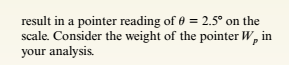
The device shown in the figure consists of a prismatic rigid pointer ABC supported by a uniform translational spring of stiffness k = 950 N/m. The spring is positioned a distance P = 165 nun from the pinned end A of the pointer. The device is adjusted so that, when there is no load P, the pointer reads zero on the angular scale.
(a) If the load P = 11 N, al what distance .v should the load be placed so that the pointer will read ?? = 2.5° on the scale (see figure part a)?
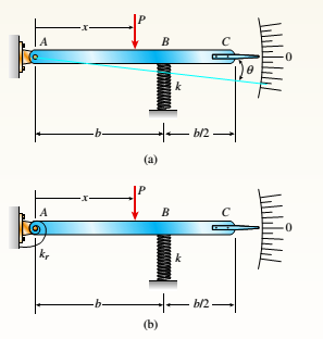
(b) Repeal part (a) if a rotational spring E1= kb-6 is added al A (see figure part b).
(c) Lel.x = 7b/8.What is P maxif 0 cannot exceed 2"? Include spring krin your analysis.
(d) Now, if the weight of the pointer ABC is known to be W =3N and the weight or the spring is Ws= 2.75 N, what initial angular position (Left in degrees) of the pointer will result in a zero reading on the angular scale once the pointer is released from rest? Assume P = kr=0.
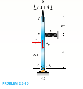
(e) If the pointer is rotated lo a vertical position (see figure part c), find the required load P applied at mid-height of the pointer that will result in a pointer reading of 0 = 2.5" on the scale. Consider the weight of the pointer W. in your analysis.
Find the equivalent torsional spring constant (up to two decimal points) of the system shown in the figure.
Given : R = 0.2 m
k1=1 kN.m/rad, k2 = 2 kN.m/rad , k3 = 3 kN.m/rad , k4 = 4 kN.m/rad , k5 = 5kN/m and k6 = 3.0 kN/m
K1
For the spring shown above,
kl=100 N/mm, k2-200N/mm, k3-100N/mm, P-500N, ul-u3-0
Find:
1. The global stiffness matrix
2. Displacements of nodes 2 and 3
A four-bar mechanism is working on horizontal plane. The second
link length is 0,5 m and makes an angle of 8=29 degrees with the
vertical line as shown in figure. Find the torque (T) in Nm must be
applied to link 4 to keep the mechanism in equilibrium against a
F=126 N force acting at E on the link 3 upward (along positive y-
axis) direction.
Allowable tolerance for your answer of this question is relatively 3
percent. So, work precisely and clear while solving it. Do not enter any
UNIT.
(If the direction of the torque is CCW, just enter the value of it
without any sign. If it has CW direction, enter "-" sign "negative
sign" before the value such as "- 12,12".)
4
AB=CD
A |
AD-BC=0.7 m
BE=EC
3
E
2
Yanıt:
Chapter 2 Solutions
Bundle: Mechanics Of Materials, Loose-leaf Version, 9th + Mindtap Engineering, 1 Term (6 Months) Printed Access Card
Need a deep-dive on the concept behind this application? Look no further. Learn more about this topic, mechanical-engineering and related others by exploring similar questions and additional content below.


 Mechanics of Materials (MindTap Course List)Mechanical EngineeringISBN:9781337093347Author:Barry J. Goodno, James M. GerePublisher:Cengage Learning