
Bundle: Mechanics Of Materials, Loose-leaf Version, 9th + Mindtap Engineering, 1 Term (6 Months) Printed Access Card
9th Edition
ISBN: 9781337594318
Author: Barry J. Goodno; James M. Gere
Publisher: Cengage Learning
expand_more
expand_more
format_list_bulleted
Videos
Textbook Question
Chapter 2, Problem 2.5.15P
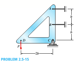
A rigid triangular frame is pivoted at C and held by two identical horizontal wires at points A and B (see figure). Each wire has an axial rigidity EA = 120 kips and coefficient of thermal expansion a = 12.5 X 10⁻⁶/°F.
(a) If a vertical load P = 500 lb acts at point D, what are the tensile forces TAand TBin the wires at A and B, respectively?
(b) If both wires have their temperatures raised by 180°F while the load P is acting, what are the forces TAand TB
(c) What further increase in temperature will cause the wire at B to become slack?
Expert Solution & Answer

Trending nowThis is a popular solution!

Chapter 2 Solutions
Bundle: Mechanics Of Materials, Loose-leaf Version, 9th + Mindtap Engineering, 1 Term (6 Months) Printed Access Card
Ch. 2 - A 10-ft rigid bar AB is supported with a vertical...Ch. 2 - Rigid bar ABC is supported with a pin at A and an...Ch. 2 - The L-shaped arm ABCD shown in the figure lies in...Ch. 2 - A steel cable with a nominal diameter of 25 mm...Ch. 2 - A steel wire- and an aluminum allay wire have...Ch. 2 - By what distance h does the cage shown in the...Ch. 2 - Rigid bar ACB is supported by an elastic circular...Ch. 2 - A plastic cylinder is held snugly between a rigid...Ch. 2 - A safety valve on the top of a tank containing...Ch. 2 - The device shown in the figure consists of a...
Ch. 2 - A small lab scale has a rigid L-shaped frame ABC...Ch. 2 - A small lab scale has a rigid L-shaped frame ABC...Ch. 2 - Two rigid bars are connected to each other by two...Ch. 2 - The three-bar truss ABC shown in the figure part a...Ch. 2 - An aluminum wire having a diameter d = 1/10 in....Ch. 2 - A uniform bar AB of weight W = 25 N is supported...Ch. 2 - A hollow, circular, cast-iron pipe (Ec =12,000...Ch. 2 - The horizon Lai rigid beam A BCD is supported by...Ch. 2 - Two pipe columns (AB, FC) are pin-connected to a...Ch. 2 - A framework ABC consists of two rigid bars AB and...Ch. 2 - Solve the preceding problem for the following...Ch. 2 - The length of the end segments of the bar (see...Ch. 2 - A long, rectangular copper bar under a tensile...Ch. 2 - An aluminum bar AD (see figure) has a...Ch. 2 - A vertical bar consists of three prismatic...Ch. 2 - A vertical bar is loaded with axial loads at...Ch. 2 - Repeat Problem 2.3-4, but now include the weight...Ch. 2 - -7 Repeat Problem 2.3-5, but n include the weight...Ch. 2 - A rectangular bar of length L has a slot in the...Ch. 2 - Solve the preceding problem if the axial stress in...Ch. 2 - A two-story building has steel columns AB in the...Ch. 2 - A steel bar is 8.0 Ft long and has a circular...Ch. 2 - A bar ABC of length L consists of two parts of...Ch. 2 - A woodpile, driven into the earth, supports a load...Ch. 2 - Consider the copper lubes joined in the strength...Ch. 2 - The nonprismalic cantilever circular bar shown has...Ch. 2 - *16 A prismatic bar AB of length L,...Ch. 2 - A flat bar of rectangular cross section, length L,...Ch. 2 - A flat brass bar has length L, constant thickness...Ch. 2 - Repeat Problem 2.3-18, but assume that the bar is...Ch. 2 - Repeat Problem 2.3-18, but assume that the bar is...Ch. 2 - A slightly tapered bar AB of solid circular crass...Ch. 2 - A circular aluminum alloy bar of length L = 1.8 m...Ch. 2 - A long, slender bar in the shape of a right...Ch. 2 - A post AB supporting equipment in a laboratory is...Ch. 2 - The main cables of a suspension bridge (see figure...Ch. 2 - A uniformly tapered lube AB of circular cross...Ch. 2 - A vertical steel bar ABC is pin-supported at its...Ch. 2 - A T-frame structure is torn posed of a prismatic...Ch. 2 - A T-frame structure is composed of prismatic beam...Ch. 2 - Repeat Problem 2.3-29 if vertical load P at D is...Ch. 2 - A bar ABC revolves in a horizontal plane about a...Ch. 2 - The assembly shown in the figure consists of a...Ch. 2 - A cylindrical assembly consisting of a brass core...Ch. 2 - A steel bar with a uniform cross section, is fixed...Ch. 2 - A horizontal rigid bar ABC is pinned at end A and...Ch. 2 - A solid circular steel cylinder S is encased in a...Ch. 2 - Three prismatic bars, two of material A and one of...Ch. 2 - A circular bar ACB of a diameter d having a...Ch. 2 - Bar ABC is fixed at both ends (see figure) and has...Ch. 2 - Repeat Problem 2.4-8, but assume that the bar is...Ch. 2 - A plastic rod AB of length L = 0.5 m has a...Ch. 2 - 2.4-11 Three steel cables jointly support a load...Ch. 2 - The fixed-end bar ABCD consists of three prismatic...Ch. 2 - A lube structure is acted on by loads at B and D,...Ch. 2 - A hollow circular pipe (see figure} support s a...Ch. 2 - The aluminum and steel pipes shown in the figure...Ch. 2 - A rigid bar of weight W = SOO N hangs from three...Ch. 2 - A bimetallic bar (or composite bar) of square...Ch. 2 - S Three-bar truss ABC (see figure) is constructed...Ch. 2 - A horizontal rigid bar of weight If' = 72001b is...Ch. 2 - A rigid bar ABCD is pinned at point B and...Ch. 2 - A rigid bar AB if of a length B = 66 in. is....Ch. 2 - Find expressions For all support reaction forces...Ch. 2 - A trimetallic bar is uniformly compressed by an...Ch. 2 - Find expressions for all support reaction Forces...Ch. 2 - The rails of a railroad track are welded together...Ch. 2 - A circular steel rod of diameter d is subjected to...Ch. 2 - A rigid bar of weight W = 750 lb hangs from three...Ch. 2 - A steel rod. of 15-mm diameter is held snugly (but...Ch. 2 - A bar AB of length L is held between rigid...Ch. 2 - A beam is constructed using two angle sections (L...Ch. 2 - A W 8 × 28 beam of a length 10 ft is held between...Ch. 2 - A plastic bar ACB having two different solid...Ch. 2 - ,5-9 A flat aluminum alloy bar is fixed at both...Ch. 2 - Repeat Problem 2.5-9 for the flat bar shown in the...Ch. 2 - A circular steel rod AB? (diameter d, = 1.0 in.,...Ch. 2 - A circular, aluminum alloy bar of a length L = 1.8...Ch. 2 - Rectangular bars of copper and aluminum are held...Ch. 2 - A brass sleeve S is fitted over a steel bolt B...Ch. 2 - A rigid triangular frame is pivoted at C and held...Ch. 2 - ,5-16 A rigid bar ABCD is pinned at end A and...Ch. 2 - A copper bar AB with a length 25 in. and diameter...Ch. 2 - A steel wire AB is stretched between rigid...Ch. 2 - -19 The mechanical assembly shown in the figure...Ch. 2 - A bar AB having a length L and axial rigidity EA...Ch. 2 - Pipe 2 has been inserted snugly into Pipe I. but...Ch. 2 - A non prism elk- bar ABC made up of segments...Ch. 2 - Wires B and C are attached to a support at the...Ch. 2 - A rigid steel plate is supported by three posts of...Ch. 2 - A capped cast-iron pipe is compressed by a brass...Ch. 2 - A plastic cylinder is held snugly between a rigid...Ch. 2 - Prob. 2.5.27PCh. 2 - Consider the sleeve made From two copper tubes...Ch. 2 - A polyethylene tube (length L) has a cap that when...Ch. 2 - Prestressed concrete beams are sometimes...Ch. 2 - Prob. 2.5.31PCh. 2 - A steel bar of rectangular cross section (1.5 in....Ch. 2 - A circular steel rod of diameter d is subjected to...Ch. 2 - A standard brick (dimensions 8 in. × 4 in. × 2.5...Ch. 2 - A brass wire of diameter d = 2.42 mm is stretched...Ch. 2 - Prob. 2.6.5PCh. 2 - A steel bar with a diameter d = 12 mm is subjected...Ch. 2 - During a tension lest of a mild-steel specimen...Ch. 2 - A copper bar with a rectangular cross section is...Ch. 2 - A prismatic bar with a length L = 3 ft and...Ch. 2 - A prismatic bar with a length L = 1 m and...Ch. 2 - The plane truss in the figure is assembled From...Ch. 2 - Plastic bar of diameter d = 32 mm is compressed in...Ch. 2 - A plastic bar of rectangular cross section (ft =...Ch. 2 - A copper bar of rectangular cross section (b = 18...Ch. 2 - A circular brass bar with a diameter J is member...Ch. 2 - Two boards are joined by gluing along a scarf...Ch. 2 - Acting on the sides of a stress element cut from a...Ch. 2 - A prismatic bar is subjected to an axial force...Ch. 2 - The normal stress on plane pq of a prismatic bar...Ch. 2 - A tension member is to be constructed of two...Ch. 2 - -21 Plastic bar AB of rectangular cross section (6...Ch. 2 - A compression bar having a square cross section...Ch. 2 - A prismatic bar AD of length L, cross-sectional...Ch. 2 - A bar with a circular cross section having two...Ch. 2 - A three-story steel column in a building supports...Ch. 2 - The bar ABC shown in the figure is loaded by a...Ch. 2 - Determine the strain energy per unit volume (units...Ch. 2 - The truss ABC shown in the Figure is subjected to...Ch. 2 - -7 The truss A BC Shawn in the figure supports a...Ch. 2 - The statically indeterminate structure shown in...Ch. 2 - A slightly tapered bar AB of rectangular cross...Ch. 2 - A compressive load P is transmitted through a...Ch. 2 - A block B is pushed against three springs by a...Ch. 2 - A bungee cord that behaves linearly elastically...Ch. 2 - A sliding collar of weight W = 150 lb falls From a...Ch. 2 - Solve the preceding problem if the collar has mass...Ch. 2 - Prob. 2.8.3PCh. 2 - A block weighing W = 5.0 N drops inside a cylinder...Ch. 2 - Solve the preceding problem for W = 1.0 lb. h = 12...Ch. 2 - Prob. 2.8.6PCh. 2 - A weight W = 4500 lb falls from a height h onto a...Ch. 2 - Prob. 2.8.8PCh. 2 - Prob. 2.8.9PCh. 2 - A bumping post at the end of a track in a railway...Ch. 2 - A bumper for a mine car is constructed with a...Ch. 2 - A bungee jumper having a mass of 55 kg leaps from...Ch. 2 - Prob. 2.8.13PCh. 2 - A rigid bar AB having a mass M = 1.0 kg and length...Ch. 2 - The flat bars shown in parts a and b of the figure...Ch. 2 - The flat bars shown in parts a and b of the figure...Ch. 2 - A flat bar of width b and thickness t has a hole...Ch. 2 - Around brass bar of a diameter d1= 20mm has upset...Ch. 2 - Prob. 2.10.5PCh. 2 - ,10-6 A prismatic bar with a diameter d0= 20 mm is...Ch. 2 - A stepped bar with a hole (see figure) has widths...Ch. 2 - A bar AB of length L and weight density y hangs...Ch. 2 - A prismatic bar of length L = 1.8 m and...Ch. 2 - Prob. 2.11.3PCh. 2 - A prismatic bar in tension has a length L = 2.0 m...Ch. 2 - An aluminum bar subjected to tensile Forces P has...Ch. 2 - A rigid bar AB is pinned al end A and is supported...Ch. 2 - Two identical bars AB and BC support a vertical...Ch. 2 - A stepped bar ACB with circular cross sections is...Ch. 2 - A horizontal rigid bar AB supporting a load P is...Ch. 2 - Prob. 2.12.4PCh. 2 - The symmetric truss ABCDE shown in the figure is...Ch. 2 - Five bars, each having a diameter of 10 mm....Ch. 2 - Prob. 2.12.7PCh. 2 - A rigid bar ACB is supported on a fulcrum at C and...Ch. 2 - The structure shown in the figure consists of a...Ch. 2 - Two cables, each having a length i. of...Ch. 2 - A hollow circular tube T of a length L = 15 in. is...
Knowledge Booster


Learn more about
Need a deep-dive on the concept behind this application? Look no further. Learn more about this topic, mechanical-engineering and related others by exploring similar questions and additional content below.Similar questions
- Truss members supporting a roof are connected to a 26-mm-thick gusset plate by a 22-mm diameter pin, as shown in the figure and photo. The two end plates on the truss members are each 14 mm thick. (a) If the load P = 80 kN, what is the largest bearing stress acting on the pin? (b) If the ultimate shear stress for the pin is 190 MPa, what force Pult is required to cause the pin to fail in shear? Disregard friction between the plates.arrow_forwardA bar AB of length L and weight density y hangs vertically under its awn weight (see figure). The stress-strain relation forth? Material is given by the Romberg-Osgood equation [Eq. (2-71)]: Derive the formula For the elongation of the bar.arrow_forwardA vertical bar is loaded with axial loads at points B, C, and D. as shown in the figure. The bar is made of steel with a modulus of elasticity E = 29,000 ksi., The bar has a cross-sectional area of 8.24 in2. Calculate the displacements at points B, C, and D. Ignore the weight of the bararrow_forward
- A plane frame is restrained al joints A and C, as shown in the figure. Members AB and BC are pin connected at B. A triangularly distributed lateral load with a peak intensity or 90 lb/ft acts on AB. A concentrated moment is applied at joint C. (a) Find reactions at supports A and C. (b) Find internal stress resultants A', V, and \f at x = 3 ft on column AB.arrow_forwardA uniform bar AB of weight W = 25 N is supported by two springs, as shown in the figure. The spring on the left has a stiffness k[= 300 N/m and natural length Lt=250 mm. The corresponding quantities for the spring on the right are k2= 400 N/m and L^ = 200 mm. The distance between the springs is L = 350 mm, and the spring on the right is suspended from a support that is a distance it = SO mm below the point of support for the spring on the left. Neglect the weight of the springs. (a) At what distance x from the left-hand spring (figure part a) should a load P = 18 N be placed in order to bring the bar to a horizontal position? (b) If P is now removed, what new value of k{is required so that the bar (figure part a) will hang in a horizontal position underweight If? (c) If P is removed and kt= 300 N/m. what distance b should spring ktbe moved to the right so that the bar (figure part a) will hang in a horizontal position under weight II"? (d) If the spring on the left is now replaced by two springs in series (kt= 300 N/m, kt) with overall natural length Lt= 250 mm (see figure part b). what value of k; is required so that the bar will hang in a horizontal position under weight IF?arrow_forwardBy what distance h does the cage shown in the figure move downward when the weight W is placed inside it? (See the figure.) Consider only the effects of the stretching of the cable, which has axial rigidity EA = 10,700 kN. The pulley at A has a diameter da= 300 mm and the pulley at B has a diameter dB= 150 mm. Also, the distance L1= 4.6 m, the distance L2=10.5 m, and the weight W = 22 kN. Note: When calculating the length of the cable. include the parts of the cable that go around the pulley sat A and B.arrow_forward
- A copper bar AB with a length 25 in. and diameter 2 in. is placed in position at room temperature with a gap of 0.008 in. between end A and a rigid restraint (see figure). The bar is supported at end B by an elastic spring with a spring constant k= 1.2 × 10⁶ lb/in. (a) Calculate the axial compressive stress crcin the bar if the temperature of the bar only rises 50 F. (For copper, use a = 9.6 × 10⁻⁶/ and E = 16 × 106 psi.) (b) What is the force in the spring? (Neglect gravity effects.) (c) Repeat part (a) if k ? 8.arrow_forwardA hollow circular pipe (see figure} support s a load P that is uniformly distributed around a cap plate at the top of the lower pipe. The inner and outer diameters of the upper and lower parts of the pipe are d1= 50 mm, d2= 60 mm, rf3 = 57 mm, and d1= 64 mm, respectively. Pipe lengths are Lt= 2 m and L, = 3 m. Neglect the self-weight of the pipes. Assume that cap plate thickness is small compared to I, and E,. Let E = 110 MPa. (a) If the tensile stress in the upper part is d = 10.5 MPa. what is load PI Also, what are reactions ft, at the upper support and R-, at the lower support? What is the stress ar(MPa) in the lower part? (b) Find displacement S(mm) at the cap plate. Plot the axial force diagram (AFD) [Ar(.f)] and axial displacement diagram (ADD)[5(.t)]. (c) Add the uniformly distributed load q along the censorial axis of pipe segment 2. Find q (kN/m) so that It, = 0. Assume that load P from part (a) is also applied.arrow_forwardA rigid bar AB having a mass M = 1.0 kg and length L = 0.5 m is hinged at end A and supported at end B by a nylon cord BC (see figure). The record has cross-sectional area A = 30 mm2. length b = 0.25 m. and modulus of elasticity E = 2.1 GPa. If the bar is raised to its maximum height and then released, what is the maximum stress in the cord?arrow_forward
- A bimetallic bar (or composite bar) of square cross sec lion with dimensions 2b X lb is construe ted of two different metals having module of elasticity E2and E2(see figure). The two parts of the bar have the same cross-sectional dimensions. The bar is compressed by forces P acting through rigid end plates. T h e line of action of t he loads has an eccentricity e of such magnitude that each part of the bar is stressed uniformly in compression. (a) Determine the axial forces Ptand P2in the two parts of the bar. (b} Determine the eccentricity e of the loads. (c) Determine the ratio C|/tr2 of the stresses in the two parts of the bar.arrow_forwardWires B and C are attached to a support at the left-hand end and to a pin-supported rigid bar at the right-hand end (see figure). Each wire has cross-sectional area A =0.03 in2 and modulus of elasticity E = 30 X 106 psi. When the bar is in a vertical position, the length of each wire is L = 80 in. However, before being attached to the bar, the length of wire B was 79.98 in. and wire C was 79.95 in. Find the tensile forces TBand Tc in the wires under the action of a force P = 700 lb acting at the upper end of the bar.arrow_forwardThe assembly shown in the figure consists of a brass core (diameter d:= 0.25 in.) surrounded by a steel shell {inner diameter d2= 0.23 in., outer diameter di= 0.35 in.}. A load .P compresses the core and shell that both have a length L = 4.0 in. The module of elasticity of the brass and steel are Eb=15 X 10fi psi and Es= 30 X 10fi psi, respectively. (a) What load P will compress the assembly by 0.003 in? (b) IF the allowable stress in the steel is 22 ksi and the allowable stress in the brass is 16 ksi. what is the allowable compressive load Pallow? (Suggestion: Use the equations derived in Example 2-8.)arrow_forward
arrow_back_ios
SEE MORE QUESTIONS
arrow_forward_ios
Recommended textbooks for you
 Mechanics of Materials (MindTap Course List)Mechanical EngineeringISBN:9781337093347Author:Barry J. Goodno, James M. GerePublisher:Cengage Learning
Mechanics of Materials (MindTap Course List)
Mechanical Engineering
ISBN:9781337093347
Author:Barry J. Goodno, James M. Gere
Publisher:Cengage Learning
Mechanical SPRING DESIGN Strategy and Restrictions in Under 15 Minutes!; Author: Less Boring Lectures;https://www.youtube.com/watch?v=dsWQrzfQt3s;License: Standard Youtube License