
POWER SYS. ANALYSIS+DESIGN
6th Edition
ISBN: 9780357700907
Author: Glover
Publisher: INTER CENG
expand_more
expand_more
format_list_bulleted
Concept explainers
Videos
Textbook Question
Chapter 2, Problem 2.31P
Consider two interconnected voltage sources connected by a line of impedance
(a) Obtain expressions for
(b) Determine the maximum power transfer and the condition for it to 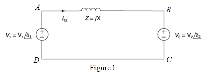
Expert Solution & Answer

Trending nowThis is a popular solution!

Students have asked these similar questions
Explain the integration of renewable energy sources, such as wind and solar, into existing power systems and the challenges associated with their intermittency.
Discuss the challenges associated with integrating renewable energy sources into the existing power system infrastructure.
A 30 mile, 3-phase transmission line delivers 8,000 kW at 33 kV, p.f. 0.8 lagging. The resistance and reactance of single conductor are 0.6 ohm and 0.72 ohm respectively per mile. Find the percent efficiency of the line.
Chapter 2 Solutions
POWER SYS. ANALYSIS+DESIGN
Ch. 2 - The rms value of v(t)=Vmaxcos(t+) is given by a....Ch. 2 - If the rms phasor of a voltage is given by V=12060...Ch. 2 - If a phasor representation of a current is given...Ch. 2 - Prob. 2.4MCQCh. 2 - Prob. 2.5MCQCh. 2 - Prob. 2.6MCQCh. 2 - Prob. 2.7MCQCh. 2 - Prob. 2.8MCQCh. 2 - Prob. 2.9MCQCh. 2 - The average value of a double-frequency sinusoid,...
Ch. 2 - The power factor for an inductive circuit (R-L...Ch. 2 - The power factor for a capacitive circuit (R-C...Ch. 2 - Prob. 2.13MCQCh. 2 - The instantaneous power absorbed by the load in a...Ch. 2 - Prob. 2.15MCQCh. 2 - With generator conyention, where the current...Ch. 2 - Consider the load convention that is used for the...Ch. 2 - Prob. 2.18MCQCh. 2 - The admittance of the impedance j12 is given by...Ch. 2 - Consider Figure 2.9 of the text, Let the nodal...Ch. 2 - The three-phase source line-to-neutral voltages...Ch. 2 - In a balanced three-phase Y-connected system with...Ch. 2 - In a balanced system, the phasor sum of the...Ch. 2 - Consider a three-phase Y-connected source feeding...Ch. 2 - For a balanced- load supplied by a balanced...Ch. 2 - A balanced -load can be converted to an...Ch. 2 - When working with balanced three-phase circuits,...Ch. 2 - The total instantaneous power delivered by a...Ch. 2 - The total instantaneous power absorbed by a...Ch. 2 - Under balanced operating conditions, consider the...Ch. 2 - One advantage of balanced three-phase systems over...Ch. 2 - While the instantaneous electric power delivered...Ch. 2 - Given the complex numbers A1=630 and A2=4+j5, (a)...Ch. 2 - Convert the following instantaneous currents to...Ch. 2 - The instantaneous voltage across a circuit element...Ch. 2 - For the single-phase circuit shown in Figure...Ch. 2 - A 60Hz, single-phase source with V=27730 volts is...Ch. 2 - (a) Transform v(t)=75cos(377t15) to phasor form....Ch. 2 - Let a 100V sinusoidal source be connected to a...Ch. 2 - Consider the circuit shown in Figure 2.23 in time...Ch. 2 - For the circuit shown in Figure 2.24, compute the...Ch. 2 - For the circuit element of Problem 2.3, calculate...Ch. 2 - Prob. 2.11PCh. 2 - The voltage v(t)=359.3cos(t)volts is applied to a...Ch. 2 - Prob. 2.13PCh. 2 - A single-phase source is applied to a...Ch. 2 - Let a voltage source v(t)=4cos(t+60) be connected...Ch. 2 - A single-phase, 120V(rms),60Hz source supplies...Ch. 2 - Consider a load impedance of Z=jwL connected to a...Ch. 2 - Let a series RLC network be connected to a source...Ch. 2 - Consider a single-phase load with an applied...Ch. 2 - A circuit consists of two impedances, Z1=2030 and...Ch. 2 - An industrial plant consisting primarily of...Ch. 2 - The real power delivered by a source to two...Ch. 2 - A single-phase source has a terminal voltage...Ch. 2 - A source supplies power to the following three...Ch. 2 - Consider the series RLC circuit of Problem 2.7 and...Ch. 2 - A small manufacturing plant is located 2 km down a...Ch. 2 - An industrial load consisting of a bank of...Ch. 2 - Three loads are connected in parallel across a...Ch. 2 - Prob. 2.29PCh. 2 - Figure 2.26 shows three loads connected in...Ch. 2 - Consider two interconnected voltage sources...Ch. 2 - Prob. 2.35PCh. 2 - Prob. 2.36PCh. 2 - Prob. 2.37PCh. 2 - Prob. 2.38PCh. 2 - Prob. 2.39PCh. 2 - A balanced three-phase 240-V source supplies a...Ch. 2 - Prob. 2.41PCh. 2 - A balanced -connected impedance load with (12+j9)...Ch. 2 - A three-phase line, which has an impedance of...Ch. 2 - Two balanced three-phase loads that are connected...Ch. 2 - Two balanced Y-connected loads, one drawing 10 kW...Ch. 2 - Three identical impedances Z=3030 are connected in...Ch. 2 - Two three-phase generators supply a three-phase...Ch. 2 - Prob. 2.48PCh. 2 - Figure 2.33 gives the general -Y transformation....Ch. 2 - Consider the balanced three-phase system shown in...Ch. 2 - A three-phase line with an impedance of...Ch. 2 - A balanced three-phase load is connected to a...Ch. 2 - What is a microgrid?Ch. 2 - What are the benefits of microgrids?Ch. 2 - Prob. CCSQCh. 2 - Prob. DCSQ
Knowledge Booster


Learn more about
Need a deep-dive on the concept behind this application? Look no further. Learn more about this topic, electrical-engineering and related others by exploring similar questions and additional content below.Similar questions
- For the circuit element of Problem 2.3, calculate (a) the instantaneous power absorbed, (b) the real power (state whether it is delivered or absorbed). (c) the reactive power (state whether delivered or absorbed). (d) the power factor (state whether lagging or leading). [Note: By convention the power factor cos() is positive. If | | is greater than 90, then the reference direction for current may be reversed, resulting in a positive value of cos() ].arrow_forwardIf for example communication power is often normalized by assuming R to be a unity in Ohms, although R may be another value in actual circuit. If the actual value of the power is required, it is worked out by de-normalization of the normalized value. Use the above to determine the instantaneous power, given time interval to be (-4,4) and x = 2 + t2.arrow_forwardDiscuss the role of FACTS (Flexible Alternating Current Transmission Systems) devices in power system control and optimization.arrow_forward
- (II) If 35 MW of power at 45 kV (rms) arrives at a town froma generator via 4.6Ω transmission lines, calculate (a) theemf at the generator end of the lines, and (b) the fractionof the power generated that is wasted in the lines.arrow_forwardDiscuss the challenges and solutions in integrating renewable energy sources into an existing power system grid.arrow_forwardWhat is the maximum length in km for a 3 phase T.L having copper conductor of 0.775 cm2 crass section over which 200 KW at unity power factor and at 3300 V are to be delivered, the efficiency if T.L is 90%, take specific resistance as 1.725 μΩ cmarrow_forward
- Discuss the challenges and solutions related to integrating renewable energy sources, like wind and solar, into existing power systems.arrow_forwardExplain the concept of FACTS (Flexible Alternating Current Transmission Systems) devices. How do they enhance the control and stability of power systems? Provide examples of FACTS devices and their applications.arrow_forwardWhat is a microgrid, and how does it function within a larger power system? What benefits does it offer in terms of reliability and sustainability?arrow_forward
- he node (busbar) and branch (line) data of a power system are provided in Table Q1.1 and Table Q1.2 respectively. All values in the tables are stated in per unit (p.u.). Using node 1 (busbar 1) as the reference (slack bus), calculate the line flows using the DC power flow method.arrow_forwarda) High Voltages are preferred for Transmission of Electricity. Why? b) Why Generation Voltage Levels are low in the range of 11 kV/ 33 kV etc? c) Why ACSR Conductors are preferred over Copper Conductors? d) Overhead Transmission Lines are preferred for Transmission of Power for Long Distances, why? e) Alternating Current is preferred over Direct Current in Power System, Why? f) Write the Installed Generation Capacity of Sultanate of Oman with current energy share of Conventional and Non-Conventional Energy Sources. g) Why the Capacitance effect is neglected in Short Transmission Line. h) Distinguish between Lumped or Distributed elements in a Transmission Line.arrow_forwardWhich of the following statements about next-generation wind energy is correct? a. They will have a lower capacity factor than current wind energy. b. Offshore wind energy will be much cheaper than onshore. c. Offshore wind has the potential for a higher capacity factor than onshore installations. d. Integrating offshore wind into existing grid infrastructure is easier than for onshore energyarrow_forward
arrow_back_ios
SEE MORE QUESTIONS
arrow_forward_ios
Recommended textbooks for you
 Power System Analysis and Design (MindTap Course ...Electrical EngineeringISBN:9781305632134Author:J. Duncan Glover, Thomas Overbye, Mulukutla S. SarmaPublisher:Cengage Learning
Power System Analysis and Design (MindTap Course ...
Electrical Engineering
ISBN:9781305632134
Author:J. Duncan Glover, Thomas Overbye, Mulukutla S. Sarma
Publisher:Cengage Learning
Maximum Power Transfer Theorem Using Nodal Analysis & Thevenin Equivalent Circuits; Author: The Organic Chemistry Tutor;https://www.youtube.com/watch?v=8CA6ZNXgI-Y;License: Standard Youtube License