
POWER SYS. ANALYSIS+DESIGN
6th Edition
ISBN: 9780357700907
Author: Glover
Publisher: INTER CENG
expand_more
expand_more
format_list_bulleted
Concept explainers
Videos
Textbook Question
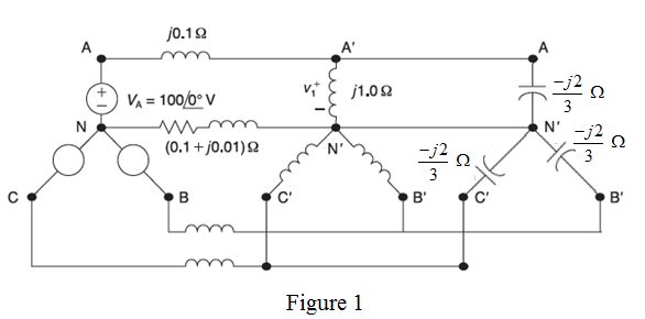
Chapter 2, Problem 2.50P
Consider the balanced three-phase system shown in Figure 2.34. Deter mine
Expert Solution & Answer

Trending nowThis is a popular solution!

Students have asked these similar questions
1. Calculate the line currents for phase a, b and c.2. Calculate the line-to-neutral voltages at the load for phase a, b and c.3. Draw the phasor diagram of the source line-to-neutral voltages and line currents.
4) State the relation between line and phase values of voltage and current for 3-pha se DELTA connected load .state the equation for active, reactive power consumed by 3-phase load.
Define the terms a) balanced system or symmetrical system b) phase
sequence c) balanced load d) phase voltage e) Line voltage
Chapter 2 Solutions
POWER SYS. ANALYSIS+DESIGN
Ch. 2 - The rms value of v(t)=Vmaxcos(t+) is given by a....Ch. 2 - If the rms phasor of a voltage is given by V=12060...Ch. 2 - If a phasor representation of a current is given...Ch. 2 - Prob. 2.4MCQCh. 2 - Prob. 2.5MCQCh. 2 - Prob. 2.6MCQCh. 2 - Prob. 2.7MCQCh. 2 - Prob. 2.8MCQCh. 2 - Prob. 2.9MCQCh. 2 - The average value of a double-frequency sinusoid,...
Ch. 2 - The power factor for an inductive circuit (R-L...Ch. 2 - The power factor for a capacitive circuit (R-C...Ch. 2 - Prob. 2.13MCQCh. 2 - The instantaneous power absorbed by the load in a...Ch. 2 - Prob. 2.15MCQCh. 2 - With generator conyention, where the current...Ch. 2 - Consider the load convention that is used for the...Ch. 2 - Prob. 2.18MCQCh. 2 - The admittance of the impedance j12 is given by...Ch. 2 - Consider Figure 2.9 of the text, Let the nodal...Ch. 2 - The three-phase source line-to-neutral voltages...Ch. 2 - In a balanced three-phase Y-connected system with...Ch. 2 - In a balanced system, the phasor sum of the...Ch. 2 - Consider a three-phase Y-connected source feeding...Ch. 2 - For a balanced- load supplied by a balanced...Ch. 2 - A balanced -load can be converted to an...Ch. 2 - When working with balanced three-phase circuits,...Ch. 2 - The total instantaneous power delivered by a...Ch. 2 - The total instantaneous power absorbed by a...Ch. 2 - Under balanced operating conditions, consider the...Ch. 2 - One advantage of balanced three-phase systems over...Ch. 2 - While the instantaneous electric power delivered...Ch. 2 - Given the complex numbers A1=630 and A2=4+j5, (a)...Ch. 2 - Convert the following instantaneous currents to...Ch. 2 - The instantaneous voltage across a circuit element...Ch. 2 - For the single-phase circuit shown in Figure...Ch. 2 - A 60Hz, single-phase source with V=27730 volts is...Ch. 2 - (a) Transform v(t)=75cos(377t15) to phasor form....Ch. 2 - Let a 100V sinusoidal source be connected to a...Ch. 2 - Consider the circuit shown in Figure 2.23 in time...Ch. 2 - For the circuit shown in Figure 2.24, compute the...Ch. 2 - For the circuit element of Problem 2.3, calculate...Ch. 2 - Prob. 2.11PCh. 2 - The voltage v(t)=359.3cos(t)volts is applied to a...Ch. 2 - Prob. 2.13PCh. 2 - A single-phase source is applied to a...Ch. 2 - Let a voltage source v(t)=4cos(t+60) be connected...Ch. 2 - A single-phase, 120V(rms),60Hz source supplies...Ch. 2 - Consider a load impedance of Z=jwL connected to a...Ch. 2 - Let a series RLC network be connected to a source...Ch. 2 - Consider a single-phase load with an applied...Ch. 2 - A circuit consists of two impedances, Z1=2030 and...Ch. 2 - An industrial plant consisting primarily of...Ch. 2 - The real power delivered by a source to two...Ch. 2 - A single-phase source has a terminal voltage...Ch. 2 - A source supplies power to the following three...Ch. 2 - Consider the series RLC circuit of Problem 2.7 and...Ch. 2 - A small manufacturing plant is located 2 km down a...Ch. 2 - An industrial load consisting of a bank of...Ch. 2 - Three loads are connected in parallel across a...Ch. 2 - Prob. 2.29PCh. 2 - Figure 2.26 shows three loads connected in...Ch. 2 - Consider two interconnected voltage sources...Ch. 2 - Prob. 2.35PCh. 2 - Prob. 2.36PCh. 2 - Prob. 2.37PCh. 2 - Prob. 2.38PCh. 2 - Prob. 2.39PCh. 2 - A balanced three-phase 240-V source supplies a...Ch. 2 - Prob. 2.41PCh. 2 - A balanced -connected impedance load with (12+j9)...Ch. 2 - A three-phase line, which has an impedance of...Ch. 2 - Two balanced three-phase loads that are connected...Ch. 2 - Two balanced Y-connected loads, one drawing 10 kW...Ch. 2 - Three identical impedances Z=3030 are connected in...Ch. 2 - Two three-phase generators supply a three-phase...Ch. 2 - Prob. 2.48PCh. 2 - Figure 2.33 gives the general -Y transformation....Ch. 2 - Consider the balanced three-phase system shown in...Ch. 2 - A three-phase line with an impedance of...Ch. 2 - A balanced three-phase load is connected to a...Ch. 2 - What is a microgrid?Ch. 2 - What are the benefits of microgrids?Ch. 2 - Prob. CCSQCh. 2 - Prob. DCSQ
Knowledge Booster


Learn more about
Need a deep-dive on the concept behind this application? Look no further. Learn more about this topic, electrical-engineering and related others by exploring similar questions and additional content below.Similar questions
- Figure 2.33 gives the general -Y transformation. (a) Show that the general transformation reduces to that given in Figure 2.16 for a balanced three-phase load. (b) Determine the impedances of the equivalent Y for the following impedances: ZAB=j10,ZBC=j20, and ZCA=j25. ZAB=ZAZB+ZBAC+ZCZAZCZA=ZABZCAZAB+ZBC+ZCAZBC=ZAZB+ZBAC+ZCZAZAZB=ZABZBCZAB+ZBC+ZCAZCA=ZAZB+ZBAC+ZCZAZBZA=ZCAZBCZAB+ZBC+ZCAarrow_forwardConsider two interconnected voltage sources connected by a line of impedance Z=jX, as shown in Figure 2.27. (a) Obtain expressions for P12 and Q12. (b) Determine the maximum power transfer and the condition for it toarrow_forwardThe three-phase source line-to-neutral voltages are given by Ean=100,Ebh=10+240, and Ecn=10240volts. Is the source balanced? (a) Yes (b) Noarrow_forward
- For the circuit element of Problem 2.3, calculate (a) the instantaneous power absorbed, (b) the real power (state whether it is delivered or absorbed). (c) the reactive power (state whether delivered or absorbed). (d) the power factor (state whether lagging or leading). [Note: By convention the power factor cos() is positive. If | | is greater than 90, then the reference direction for current may be reversed, resulting in a positive value of cos() ].arrow_forwardWith generator conyention, where the current leaves the positive terminal of the circuit element, if P is positive then positive real power is delivered. (a) False (b) Truearrow_forwardIn the figure, the circuit is given as VRS =√3 . 60V and Zy = 6 + j8. Find the value of C to be connected in order to make the power drawn from the system in a phase 1, to make the load current 1, and to make cos(φ) 1.arrow_forward
- A three phase system cannot be obtained using two single phase source. True Falsearrow_forwardAn AC three phase distribution system (given in Figure 2), which has end user with balanced three phase (10A) load, is given in the figure. The phase-neutral voltages of the transformers are given as V1=224V, V2=225V, V3=228V and V4=231V respectively. a) Calculate phase-neutral voltage of the bus-bar (B). b) Calculate currents of the transformers (I1, I2, I3 and I4) c) Calculate phase-neutral voltage of the point K while the output of TR3 and TR4 (xy) have been short circuited for a transient time (transformers are still operational) by the line fault.arrow_forwardWrite an introduction about: LOAD BALANCING in 3-Phase Systemarrow_forward
- Describe the concept of three-phase power in electrical systems and its significance in power distribution.arrow_forwardDefine the terms a) balanced system or symmetrical system b) phase sequence c) balanced load d) unbalanced load. e) Line voltage f) phase voltage g) Line current h) phase voltagearrow_forwardThe power system insulation problem involves a. Capacitance of earth and subsequent grounding b. Selection of basic insulation level of system equipment c. Determination of single phase line insulation d. Determination of three phase line insulation Clear my choicearrow_forward
arrow_back_ios
SEE MORE QUESTIONS
arrow_forward_ios
Recommended textbooks for you
 Power System Analysis and Design (MindTap Course ...Electrical EngineeringISBN:9781305632134Author:J. Duncan Glover, Thomas Overbye, Mulukutla S. SarmaPublisher:Cengage Learning
Power System Analysis and Design (MindTap Course ...
Electrical Engineering
ISBN:9781305632134
Author:J. Duncan Glover, Thomas Overbye, Mulukutla S. Sarma
Publisher:Cengage Learning
Fault Analysis in Power Systems part 1a; Author: GeneralPAC: Power System Tutorials;https://www.youtube.com/watch?v=g8itg4MOjok;License: Standard youtube license