
ANALYSIS+DESIGN OF LINEAR CIRCUITS(LL)
8th Edition
ISBN: 9781119235385
Author: Thomas
Publisher: WILEY
expand_more
expand_more
format_list_bulleted
Concept explainers
Videos
Textbook Question
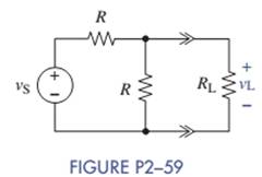
Chapter 2, Problem 2.59P
Use voltage division in Figure P2-59 to obtain an expression for
Expert Solution & Answer
Want to see the full answer?
Check out a sample textbook solution
Students have asked these similar questions
Say you were trying to find the equivalent resistance based on this circuit. How would v1 be found? (a specific value wouldn't be needed, just the step-by-step process to find the values.)
The 12-V source in Figure P2.32 is delivering 36 mW of power. All four resistors have the same value R. Find the value of R.
The voltage divider network of Figure P2.58 isexpected to provide 5 V at the output. The resistors,however, may not be exactly the same; that is, theirtolerances are such that the resistances may not beexactly 5 k.a. If the resistors have ±10 percent tolerance, find theworst-case output voltages.b. Find these voltages for tolerances of ±5 percent.Given: V = 10 V, R1 = 5 k, R2 = 5 k.
Chapter 2 Solutions
ANALYSIS+DESIGN OF LINEAR CIRCUITS(LL)
Ch. 2 - Prob. 2.1PCh. 2 - The voltage across a particular resistor is 8.60 V...Ch. 2 - You can choose to connect either a 4.7-k resistor...Ch. 2 - A model railroader wants to be able to...Ch. 2 - A 100-k resistor dissipates 50mW. Find the current...Ch. 2 - The conductance of a particular semiconductor...Ch. 2 - In Figure P2—7 the resistor dissipates 25 mW. Find...Ch. 2 - In Figure P2—8 find Rx and the power supplied by...Ch. 2 - A resistor found in the lab has three orange...Ch. 2 - The iv characteristic of a nonlinear resistor is...
Ch. 2 - A 100-k resistor has a power rating of 0.25 W....Ch. 2 - A certain type of film resistor is available with...Ch. 2 - Figure P2—13 shows the circuit symbol for a class...Ch. 2 - A thermistor is a temperature-sensing element...Ch. 2 - In Figure P2-15i2=6A and i3=2A. Find i1 and i4.Ch. 2 - In Figure P2-16 determine which elements are in...Ch. 2 - For the circuit in Figure P2—17: Identify the...Ch. 2 - In Figure P2-17 i2=30mA and i4=20mA. Find i1 and...Ch. 2 - For the circuit in Figure P2—19: Identify the...Ch. 2 - In Figure P2-19 v2=20V,v3=20V, and v4=6V. Find...Ch. 2 - In many circuits the ground is often the metal...Ch. 2 - The circuit in figure P2-22 is organized around...Ch. 2 - Are any of the elements in Figure P2-23 in series...Ch. 2 - Are any of the elements in Figure P2-24 in series...Ch. 2 - Use the passive sign convention to assign voltage...Ch. 2 - If a wire is connected between nodes B and C in...Ch. 2 - The KCL equations for a three-node circuit are as...Ch. 2 - For the circuit in Figure P2—28, write a complete...Ch. 2 - For the circuit in Figure P2—29, write a complete...Ch. 2 - Find vx and ix in Figure P2-30. Compare the...Ch. 2 - A modeler wants to light his model building using...Ch. 2 - Find vx and ix in Figure P2-32.Ch. 2 - In Figure P2-33: Assign a voltage and current...Ch. 2 - Find vO in the circuit of Figure P2-34.Ch. 2 - Find the power provided by the source in Figure...Ch. 2 - Figure P2-36 shows a subcircuit connected to the...Ch. 2 - In Figure P2-37 ix=0.33mA. Find the value of R.Ch. 2 - Figure P2—38 shows a resistor with one terminal...Ch. 2 - Find the equivalent resistant REQ in Figure P2-39.Ch. 2 - Find the equivalent R EQ in Figure P2-40.Ch. 2 - Find the equivalent resistance REQ in Figure...Ch. 2 - Equivalent resistance is defined at a particular...Ch. 2 - Find REQ in Figure P2—43 when the switch is open....Ch. 2 - Find REQ between nodes A and B for each of the...Ch. 2 - Show how the circuit in Figure P2—45 could be...Ch. 2 - In Figure P2-46 find the equivalent resistance...Ch. 2 - In Figure P2-47 find the equivalent resistance...Ch. 2 - Select a value of RL in Figure P2-48 so that...Ch. 2 - Using no more than four 1-k resistors, show how...Ch. 2 - Do a source transformation at terminals A and B...Ch. 2 - For each of the circuits in Figure P2-51, find the...Ch. 2 - In Figure P2-52, the iv characteristic of network...Ch. 2 - Select the value of Rx in Figure P2-53 so that...Ch. 2 - Two 10-k potentiometers (a variable resistor whose...Ch. 2 - Select the value of R in Figure P2-55 so that...Ch. 2 - What is the range of REQ in Figure P2-56?Ch. 2 - Find the equivalent resistance between terminals A...Ch. 2 - Use voltage division in Figure P2-58 to find...Ch. 2 - Use voltage division in Figure P2-59 to obtain an...Ch. 2 - Use current division in Figure P2-60 to find...Ch. 2 - Use current division in Figure P2-61 to find an...Ch. 2 - Find ix,iy, and iz in Figure P2-62.Ch. 2 - Find vO in the circuit of Figure P2-63.Ch. 2 - You wish to drive a 1-k load from your car battery...Ch. 2 - Find the range of values of vo in Figure P2-65.Ch. 2 - Use current division in the circuit of Figure...Ch. 2 - Figure P2-67 shows a voltage bridge circuit, that...Ch. 2 - A Ideally, a voltmeter has infinite internal...Ch. 2 - Select values for R1,R2, and R3 in Figure P2-69 so...Ch. 2 - Select a value of Rx in Figure P2-70 so that...Ch. 2 - Select a value of Rx in Figure P2-71 so that...Ch. 2 - Use circuit reduction to find vx and ix in Figure...Ch. 2 - Use circuit reduction to find vx,ix, and px in...Ch. 2 - Use circuit reduction to find vx and ix in Figure...Ch. 2 - Use circuit reduction to find vx,ix, and px in...Ch. 2 - Use circuit reduction to find vx and ix in Figure...Ch. 2 - Use source transformation to find ix in Figure...Ch. 2 - Select a value for Rx so that ix=0A in Figure...Ch. 2 - Use source transformations in Figure P2-79 to...Ch. 2 - The current through RL in figure P2-80 is 100mA....Ch. 2 - Select Rx so that 50 V is across it in Figure...Ch. 2 - The box in the circuit in Figure P2-82 is a...Ch. 2 - A circuit is found to have the following element...Ch. 2 - Consider the circuit of Figure P2-88. Use MATLAB...Ch. 2 - Nonlinear Device Characteristics The circuit in...Ch. 2 - Prob. 2.92IPCh. 2 - Center Tapped Voltage Divider Figure P2-93 shows a...Ch. 2 - Active Transducer Figure P2-95 shows an active...Ch. 2 - Programmable Voltage Divider Figure P2-97 shows a...Ch. 2 - Analog Voltmeter Design Figure P2-98(a) shows a...Ch. 2 - MATLAB Function for Parallel Equivalent Resistors...
Knowledge Booster


Learn more about
Need a deep-dive on the concept behind this application? Look no further. Learn more about this topic, electrical-engineering and related others by exploring similar questions and additional content below.Similar questions
- The coil of a measuring instrument has a resistance of 1-ohm and the instrument has a full scale deflection of 250 V when a resistance of 4999 is connected with it. Draw a circuit by using given data and Solve it to find the full scale current of the PMMC meter when used as voltmeter.arrow_forwardConsider the circuit in the given figure. Find the equivalent resistance at terminals: (a) a-b, (b) c-d. Assume R1 = 10 Ω and R2 = 90 Ω. The equivalent resistance at terminal a-b is ______ Ω. The equivalent resistance at terminal c-d is ________Ω.arrow_forwardFind the equivalent resistance between terminals aand b in the circuit of Figure P2.47.arrow_forward
- Resistors R1 and R2 dissipate 100 W and 75 W respectively across a 100-V DC source. If the two resistors are reconnected in series across a 150-V DC source, find the voltage across the resistors.arrow_forwardThe equivalent resistance between terminals a and b in Figure P2.17 is Rab=23 Ω.Determine the value of R.arrow_forwardFind the values of v and i in Figure P2.25.arrow_forward
- A studrnt wants to measure the voltage across the resistor R2 // R3 for the circuit below. Where should a student hook up a voltmeter to measure the voltage across R2 // R3?arrow_forwardFind the equivalent resistances of the circuits in the figure (when viewed from the source) andCalculate the power.arrow_forwardSuppose we need to design a voltage-divider circuit to provide an output voltage vo = 5V from a 15-V source as shown in Figure P2.40. The current taken from the 15-V source is to be 200 mA. a. Find the values of R1 and R2. b. Now suppose that a load resistance of 200 Ω is connected across the output terminals (i.e., in parallel with R2 ). Find the value of vo.arrow_forward
- There is a collection of 100 ohms and 10 ohms resistors. Design a circuit, with min number of resistors only with those, that R_eq = 265 ohms.arrow_forwardFind the values of I2 and I3 that will make the output voltage (OUT) to 0.5v. Describe the approach taken in solving the problem. Indicate the range of I2 and I3 used to solve the problem.Describe the relationship between I2 and I3 with respect to the output voltage.arrow_forwardUse superposition to find the current i in Figure P2.94. First, zero the current source and find the value iv caused by the voltage source alone. Then, zero the voltage source and find the value caused by the current source alone. Finally, add the results algebraically.arrow_forward
arrow_back_ios
SEE MORE QUESTIONS
arrow_forward_ios
Recommended textbooks for you
 Introductory Circuit Analysis (13th Edition)Electrical EngineeringISBN:9780133923605Author:Robert L. BoylestadPublisher:PEARSON
 Delmar's Standard Textbook Of ElectricityElectrical EngineeringISBN:9781337900348Author:Stephen L. HermanPublisher:Cengage Learning
 Programmable Logic ControllersElectrical EngineeringISBN:9780073373843Author:Frank D. PetruzellaPublisher:McGraw-Hill Education
 Fundamentals of Electric CircuitsElectrical EngineeringISBN:9780078028229Author:Charles K Alexander, Matthew SadikuPublisher:McGraw-Hill Education
 Electric Circuits. (11th Edition)Electrical EngineeringISBN:9780134746968Author:James W. Nilsson, Susan RiedelPublisher:PEARSON
 Engineering ElectromagneticsElectrical EngineeringISBN:9780078028151Author:Hayt, William H. (william Hart), Jr, BUCK, John A.Publisher:Mcgraw-hill Education,
Introductory Circuit Analysis (13th Edition)
Electrical Engineering
ISBN:9780133923605
Author:Robert L. Boylestad
Publisher:PEARSON
Delmar's Standard Textbook Of Electricity
Electrical Engineering
ISBN:9781337900348
Author:Stephen L. Herman
Publisher:Cengage Learning
Programmable Logic Controllers
Electrical Engineering
ISBN:9780073373843
Author:Frank D. Petruzella
Publisher:McGraw-Hill Education
Fundamentals of Electric Circuits
Electrical Engineering
ISBN:9780078028229
Author:Charles K Alexander, Matthew Sadiku
Publisher:McGraw-Hill Education
Electric Circuits. (11th Edition)
Electrical Engineering
ISBN:9780134746968
Author:James W. Nilsson, Susan Riedel
Publisher:PEARSON
Engineering Electromagnetics
Electrical Engineering
ISBN:9780078028151
Author:Hayt, William H. (william Hart), Jr, BUCK, John A.
Publisher:Mcgraw-hill Education,
Nodal Analysis for Circuits Explained; Author: Engineer4Free;https://www.youtube.com/watch?v=f-sbANgw4fo;License: Standard Youtube License