
ANALYSIS+DESIGN OF LINEAR CIRCUITS(LL)
8th Edition
ISBN: 9781119235385
Author: Thomas
Publisher: WILEY
expand_more
expand_more
format_list_bulleted
Videos
Textbook Question
Chapter 2, Problem 2.93IP
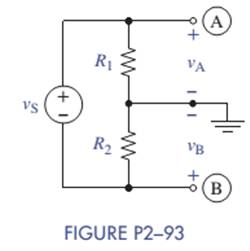
Center Tapped Voltage Divider
Figure P2-93 shows a voltage divider with the center tap connected to ground. Derive equations relating
Expert Solution & Answer
Want to see the full answer?
Check out a sample textbook solution
Students have asked these similar questions
Find the values of the resistors R1, R2, R3, R4, R5, the currents passing through these resistors and power of these resistors.
Solve for i2, v2, and p2 in the 50 Resistor
A power supply with an internal resistance of 10 Ω delivers power to a resistive load. If the no load voltage at the output of the supply is 50 V, determine the load resistance RL if the power delivered to the load is at maximum. What is the maximum power equal to?
Chapter 2 Solutions
ANALYSIS+DESIGN OF LINEAR CIRCUITS(LL)
Ch. 2 - Prob. 2.1PCh. 2 - The voltage across a particular resistor is 8.60 V...Ch. 2 - You can choose to connect either a 4.7-k resistor...Ch. 2 - A model railroader wants to be able to...Ch. 2 - A 100-k resistor dissipates 50mW. Find the current...Ch. 2 - The conductance of a particular semiconductor...Ch. 2 - In Figure P2—7 the resistor dissipates 25 mW. Find...Ch. 2 - In Figure P2—8 find Rx and the power supplied by...Ch. 2 - A resistor found in the lab has three orange...Ch. 2 - The iv characteristic of a nonlinear resistor is...
Ch. 2 - A 100-k resistor has a power rating of 0.25 W....Ch. 2 - A certain type of film resistor is available with...Ch. 2 - Figure P2—13 shows the circuit symbol for a class...Ch. 2 - A thermistor is a temperature-sensing element...Ch. 2 - In Figure P2-15i2=6A and i3=2A. Find i1 and i4.Ch. 2 - In Figure P2-16 determine which elements are in...Ch. 2 - For the circuit in Figure P2—17: Identify the...Ch. 2 - In Figure P2-17 i2=30mA and i4=20mA. Find i1 and...Ch. 2 - For the circuit in Figure P2—19: Identify the...Ch. 2 - In Figure P2-19 v2=20V,v3=20V, and v4=6V. Find...Ch. 2 - In many circuits the ground is often the metal...Ch. 2 - The circuit in figure P2-22 is organized around...Ch. 2 - Are any of the elements in Figure P2-23 in series...Ch. 2 - Are any of the elements in Figure P2-24 in series...Ch. 2 - Use the passive sign convention to assign voltage...Ch. 2 - If a wire is connected between nodes B and C in...Ch. 2 - The KCL equations for a three-node circuit are as...Ch. 2 - For the circuit in Figure P2—28, write a complete...Ch. 2 - For the circuit in Figure P2—29, write a complete...Ch. 2 - Find vx and ix in Figure P2-30. Compare the...Ch. 2 - A modeler wants to light his model building using...Ch. 2 - Find vx and ix in Figure P2-32.Ch. 2 - In Figure P2-33: Assign a voltage and current...Ch. 2 - Find vO in the circuit of Figure P2-34.Ch. 2 - Find the power provided by the source in Figure...Ch. 2 - Figure P2-36 shows a subcircuit connected to the...Ch. 2 - In Figure P2-37 ix=0.33mA. Find the value of R.Ch. 2 - Figure P2—38 shows a resistor with one terminal...Ch. 2 - Find the equivalent resistant REQ in Figure P2-39.Ch. 2 - Find the equivalent R EQ in Figure P2-40.Ch. 2 - Find the equivalent resistance REQ in Figure...Ch. 2 - Equivalent resistance is defined at a particular...Ch. 2 - Find REQ in Figure P2—43 when the switch is open....Ch. 2 - Find REQ between nodes A and B for each of the...Ch. 2 - Show how the circuit in Figure P2—45 could be...Ch. 2 - In Figure P2-46 find the equivalent resistance...Ch. 2 - In Figure P2-47 find the equivalent resistance...Ch. 2 - Select a value of RL in Figure P2-48 so that...Ch. 2 - Using no more than four 1-k resistors, show how...Ch. 2 - Do a source transformation at terminals A and B...Ch. 2 - For each of the circuits in Figure P2-51, find the...Ch. 2 - In Figure P2-52, the iv characteristic of network...Ch. 2 - Select the value of Rx in Figure P2-53 so that...Ch. 2 - Two 10-k potentiometers (a variable resistor whose...Ch. 2 - Select the value of R in Figure P2-55 so that...Ch. 2 - What is the range of REQ in Figure P2-56?Ch. 2 - Find the equivalent resistance between terminals A...Ch. 2 - Use voltage division in Figure P2-58 to find...Ch. 2 - Use voltage division in Figure P2-59 to obtain an...Ch. 2 - Use current division in Figure P2-60 to find...Ch. 2 - Use current division in Figure P2-61 to find an...Ch. 2 - Find ix,iy, and iz in Figure P2-62.Ch. 2 - Find vO in the circuit of Figure P2-63.Ch. 2 - You wish to drive a 1-k load from your car battery...Ch. 2 - Find the range of values of vo in Figure P2-65.Ch. 2 - Use current division in the circuit of Figure...Ch. 2 - Figure P2-67 shows a voltage bridge circuit, that...Ch. 2 - A Ideally, a voltmeter has infinite internal...Ch. 2 - Select values for R1,R2, and R3 in Figure P2-69 so...Ch. 2 - Select a value of Rx in Figure P2-70 so that...Ch. 2 - Select a value of Rx in Figure P2-71 so that...Ch. 2 - Use circuit reduction to find vx and ix in Figure...Ch. 2 - Use circuit reduction to find vx,ix, and px in...Ch. 2 - Use circuit reduction to find vx and ix in Figure...Ch. 2 - Use circuit reduction to find vx,ix, and px in...Ch. 2 - Use circuit reduction to find vx and ix in Figure...Ch. 2 - Use source transformation to find ix in Figure...Ch. 2 - Select a value for Rx so that ix=0A in Figure...Ch. 2 - Use source transformations in Figure P2-79 to...Ch. 2 - The current through RL in figure P2-80 is 100mA....Ch. 2 - Select Rx so that 50 V is across it in Figure...Ch. 2 - The box in the circuit in Figure P2-82 is a...Ch. 2 - A circuit is found to have the following element...Ch. 2 - Consider the circuit of Figure P2-88. Use MATLAB...Ch. 2 - Nonlinear Device Characteristics The circuit in...Ch. 2 - Prob. 2.92IPCh. 2 - Center Tapped Voltage Divider Figure P2-93 shows a...Ch. 2 - Active Transducer Figure P2-95 shows an active...Ch. 2 - Programmable Voltage Divider Figure P2-97 shows a...Ch. 2 - Analog Voltmeter Design Figure P2-98(a) shows a...Ch. 2 - MATLAB Function for Parallel Equivalent Resistors...
Knowledge Booster


Learn more about
Need a deep-dive on the concept behind this application? Look no further. Learn more about this topic, electrical-engineering and related others by exploring similar questions and additional content below.Similar questions
- If two resistors are connected in parallel and R1 is shorted, what are the current and voltage in R2? Explain If two resistors are connected in parallel and R1 is open, what are the current and voltage in R2? Explain Which has more excellent equivalent resistance, those resistors in parallel or those in series? Explainarrow_forwardDetermine the equivalent resistance between terminals a and b in Figure T2.7arrow_forwardA basic D’ Arsonval movement with a full-scale deflection of 66 uA and internal resistance of 480Ω is used as a DC voltmeter. Determine the value of the multiplier resistance needed to measure a voltage range of 0-11V (in ohms).arrow_forward
- Figure shows the resistors from the previous two examples wired in a different way—a combination of series and parallel. We can consider R1 to be the resistance of wires leading to R2 and R3 . Find the current I2 through R2.arrow_forwardTwo resistors R1 and R2 are connected in series and values of resistance are give.What is uncertainty when they connected in series.arrow_forwardShow All work in the figure shown below determine if the following statement is correct based on the mesh analysis technique: The value of the current i2 = -5A True or falsearrow_forward
- Write a set of equations that can be used to solve for the mesh currents of Figure T2.4. Be sure to indicate which of the equations you write form the set.arrow_forwardWe can model a certain battery as a voltage source in series with a resistance. The open-circuit voltage of the battery is 9 V. When a 100-Ω resistor is placed across the terminals of the battery, the voltage drops to 6 V. Determine the internal resistance (Thévenin resistance) of the battery.arrow_forwardWe have a load resistance of 50 Ω that we wish to supply with 5 V. A 12.6-V voltage source and resistors of any value needed are available. Draw a suitable circuit consisting of the voltage source, the load, and one additional resistor. Specify the value of the resistor.arrow_forward
- you have a voltmeter and ammeter to measure the unknown resistance suggest the best way to measure the resistance if the value of this resistance a/very high. b/ very low. Draw and discuss briefly the circuit diagramsarrow_forwarda student wants to measure the voltage across the resistor R2//R3 for the circuit below. Where should a student hook up a voltmeter to measure the voltage across R2//R3?arrow_forwardb. When you use an instrument like an Ammeter to measure current in an electrical circuit the measured value of the current is not the actual value of the current. What is the main reason for this? State a mathematical expression that can be used to measure this effect. What measure would you take to reduce this problem?c. An Ammeter with an Internal resistance 200Ω is used to measure the current in a circuit with three resistances in series. The values of the three resistances are 100Ω, 200Ω and 400Ω respectively. There is a single power supply with a value of 12V connected in series with the three resistors. Using the expression you have stated in (b) obtain the loading effect when measuring the current of this circuit.arrow_forward
arrow_back_ios
SEE MORE QUESTIONS
arrow_forward_ios
Recommended textbooks for you
 Introductory Circuit Analysis (13th Edition)Electrical EngineeringISBN:9780133923605Author:Robert L. BoylestadPublisher:PEARSON
 Delmar's Standard Textbook Of ElectricityElectrical EngineeringISBN:9781337900348Author:Stephen L. HermanPublisher:Cengage Learning
 Programmable Logic ControllersElectrical EngineeringISBN:9780073373843Author:Frank D. PetruzellaPublisher:McGraw-Hill Education
 Fundamentals of Electric CircuitsElectrical EngineeringISBN:9780078028229Author:Charles K Alexander, Matthew SadikuPublisher:McGraw-Hill Education
 Electric Circuits. (11th Edition)Electrical EngineeringISBN:9780134746968Author:James W. Nilsson, Susan RiedelPublisher:PEARSON
 Engineering ElectromagneticsElectrical EngineeringISBN:9780078028151Author:Hayt, William H. (william Hart), Jr, BUCK, John A.Publisher:Mcgraw-hill Education,
Introductory Circuit Analysis (13th Edition)
Electrical Engineering
ISBN:9780133923605
Author:Robert L. Boylestad
Publisher:PEARSON
Delmar's Standard Textbook Of Electricity
Electrical Engineering
ISBN:9781337900348
Author:Stephen L. Herman
Publisher:Cengage Learning
Programmable Logic Controllers
Electrical Engineering
ISBN:9780073373843
Author:Frank D. Petruzella
Publisher:McGraw-Hill Education
Fundamentals of Electric Circuits
Electrical Engineering
ISBN:9780078028229
Author:Charles K Alexander, Matthew Sadiku
Publisher:McGraw-Hill Education
Electric Circuits. (11th Edition)
Electrical Engineering
ISBN:9780134746968
Author:James W. Nilsson, Susan Riedel
Publisher:PEARSON
Engineering Electromagnetics
Electrical Engineering
ISBN:9780078028151
Author:Hayt, William H. (william Hart), Jr, BUCK, John A.
Publisher:Mcgraw-hill Education,
Lesson 2 - Source Transformations, Part 2 (Engineering Circuits); Author: Math and Science;https://www.youtube.com/watch?v=7gno74RhVGQ;License: Standard Youtube License