
Fundamentals of Applied Electromagnetics (7th Edition)
7th Edition
ISBN: 9780133356816
Author: Fawwaz T. Ulaby, Umberto Ravaioli
Publisher: PEARSON
expand_more
expand_more
format_list_bulleted
Concept explainers
Videos
Textbook Question
Chapter 2, Problem 3P
Show that the transmission-line model shown in Fig. P2.3 yields the same telegrapher’s equations given by Eqs. (2.14) and (2.16).
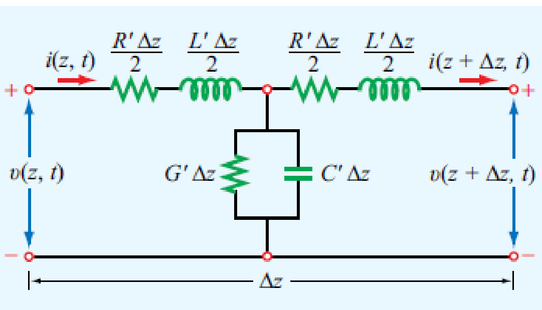
Figure P2.3 Transmission-line model for Problem 2.3.
Expert Solution & Answer

Trending nowThis is a popular solution!

Students have asked these similar questions
A transmission line is supported from two towers at heights of 40 m and 58 m above ground level, the horizontal distance between the towers being 300 m. If the maximum allowable tension is 2500 kg, find the minimum clearance and the clearance at a point mid-way between the towers. Weight of conductor is 1 kg/m.
A distortionless transmission line has a resistance per unit length of 0.5 ohm/m. If the characteristic impedance of the line is 50 ohm, them what will be the attenuation constant of the line in Neper (Np)/m?
7. Two towers of height 40 m and 30 m respectively support a transmission line conductor at water crossing. The horizontal distance between the towers is 300 m. If the tension in the conductor is 1590 kg, find the clearance of the conductor at a point mid-way between the supports. Weight of conductor is 0·8 kg/m. Bases of the towers can be considered to be at the water level.
Chapter 2 Solutions
Fundamentals of Applied Electromagnetics (7th Edition)
Ch. 2.2 - What is a transmission line? When should...Ch. 2.2 - Prob. 2CQCh. 2.2 - What constitutes a TEM transmission line?Ch. 2.2 - Prob. 4CQCh. 2.2 - Prob. 1ECh. 2.2 - Calculate the transmission line parameters at 1...Ch. 2.4 - Verify that Eq. (2.26a) indeed provides a solution...Ch. 2.4 - A two-wire air line has the following line...Ch. 2.6 - The attenuation constant represents ohmic losses....Ch. 2.6 - How is the wavelength of the wave traveling on...
Ch. 2.6 - Prob. 7CQCh. 2.6 - What is a standing-wave pattern? Why is its period...Ch. 2.6 - Prob. 9CQCh. 2.6 - For a lossless transmission line, = 20.7 cm at 1...Ch. 2.6 - A lossless transmission line uses a dielectric...Ch. 2.6 - Prob. 7ECh. 2.6 - Prob. 8ECh. 2.6 - Prob. 10ECh. 2.6 - A 140 lossless line is terminated in a load...Ch. 2.8 - What is the difference between the characteristic...Ch. 2.8 - What is a quarter-wave transformer? How can it be...Ch. 2.8 - Prob. 12CQCh. 2.8 - Prob. 13CQCh. 2.8 - if the input impedance of a lossless line is...Ch. 2.8 - Prob. 12ECh. 2.8 - A 300 feedline is to be connected to a 3 m long,...Ch. 2.9 - According to Eq. (2.102b), the instantaneous value...Ch. 2.9 - Prob. 16CQCh. 2.9 - What fraction of the incident power is delivered...Ch. 2.9 - Prob. 18CQCh. 2.9 - For a 50 lossless transmission line terminated in...Ch. 2.9 - For the line of Exercise 2-14, what is the...Ch. 2.10 - The outer perimeter of the Smith chart represents...Ch. 2.10 - What is an SWR circle? What quantities are...Ch. 2.10 - What line length corresponds to one complete...Ch. 2.10 - Which points on the SWR circle correspond to...Ch. 2.10 - Prob. 23CQCh. 2.10 - Use the Smith chart to find the values of ...Ch. 2.11 - Prob. 24CQCh. 2.11 - Prob. 25CQCh. 2.12 - What is transient analysis used for?Ch. 2.12 - Prob. 28CQCh. 2.12 - What is the difference between the bounce diagram...Ch. 2 - A transmission line of length l connects a load to...Ch. 2 - Show that the transmission-line model shown in...Ch. 2 - A 1 GHz parallel-plate transmission line consists...Ch. 2 - For the parallel-plate transmission line of...Ch. 2 - In addition to not dissipating power, a lossless...Ch. 2 - For a distortionless line [see Problem 2.13] with...Ch. 2 - Prob. 15PCh. 2 - A transmission line operating at 125 MHz has Z0 =...Ch. 2 - Prob. 17PCh. 2 - Polyethylene with r=2.25 is used as the insulating...Ch. 2 - Prob. 20PCh. 2 - Prob. 21PCh. 2 - Prob. 22PCh. 2 - Prob. 23PCh. 2 - A 50 lossless line terminated in a purely...Ch. 2 - Prob. 26PCh. 2 - Prob. 27PCh. 2 - Prob. 29PCh. 2 - Prob. 30PCh. 2 - Two half-wave dipole antennas, each with an...Ch. 2 - Prob. 34PCh. 2 - For the lossless transmission line circuit shown...Ch. 2 - A lossless transmission line is terminated in a...Ch. 2 - The input impedance of a 31 cm long lossless...Ch. 2 - FM broadcast station uses a 300 transmission line...Ch. 2 - A generator with Vg=300 V and Zg = 50 is...Ch. 2 - If the two-antenna configuration shown in Fig....Ch. 2 - For the circuit shown in Fig. P2.44, calculate the...Ch. 2 - The circuit shown in Fig. P2.45 consists of a 100 ...Ch. 2 - An antenna with a load impedance ZL=(75+j25) is...Ch. 2 - Prob. 47PCh. 2 - Use the Smith chart to determine the input...Ch. 2 - Prob. 52PCh. 2 - A lossless 50 transmission line is terminated in...Ch. 2 - A lossless 50 transmission line is terminated in...Ch. 2 - Use the Smith chart to find yL if zL = 1.5 j0.7.Ch. 2 - Prob. 59PCh. 2 - Prob. 62PCh. 2 - Determine Zin of the feed line shown in Fig....Ch. 2 - Prob. 73PCh. 2 - A 25 antenna is connected to a 75 lossless...Ch. 2 - Prob. 75PCh. 2 - Prob. 76PCh. 2 - Prob. 77PCh. 2 - In response to a step voltage, the voltage...Ch. 2 - Suppose the voltage waveform shown in Fig. P2.77...Ch. 2 - For the circuit of Problem 2.80, generate a bounce...Ch. 2 - In response to a step voltage, the voltage...
Knowledge Booster


Learn more about
Need a deep-dive on the concept behind this application? Look no further. Learn more about this topic, electrical-engineering and related others by exploring similar questions and additional content below.Similar questions
- Calculate the capacitance-to-neutral in F/m and the admittance-to-neutral in S/km for the three-phase line in Problem 4.18. Also calculate the line-charging current in kA/phase if the line is 110 km in length and is operated at 230 kV. Neglect the effect of the earth plane.arrow_forwardA 300 km long 3-phase transmission line of 154 kV is operated at 60 Hz. The line is on average 1200 m above sea level and instead At 120m, an air outlet decreases by 10 mmHg. Sea free air the dose is 760 mmHg and the puncture strength of the air is 30 kV / cm As it is known, the roughness of the line is 0.89 for the average outdoor temperature of 34 oC, The distance between the conductors is 550 cm and the conductor cross section is 40mm. along the line by calculating the corona voltage and corona discharge voltage calculate the total corona loss that occurred.arrow_forwardA three-phase power of 460 MW is transmitted to a substation located 500 km from the source of power. With VS=1 per unit, VR=0.9 per unit, λ =5000 km, Zc =500 V, and δ=36.878, determine a nominal voltagen level for the lossless transmission line based on Eq. (5.4.29) of the text. Using this result, find the theoretical three-phase maximum power that can be transferred by the lossless transmission line.arrow_forward
- For the lossless transmission line shown below, the T.L. was previously charged to E=128V and the switch is closed at t=0. If Zo= 150 ohms and RL= 450 ohms, find the following VRL at t=3To VRL at t=To First reflected voltage from the load (Vr-)arrow_forwardAn overhead transmission line at a river crossing is supported from two towers at heights of 50 m and 100 m above the water level. The horizontal distance between the towers is 400 m. If the maximum allowable tension is 1800 kg and the conductor weighs 1 kg/m, Analyze the clearance between the conductor and water at a point mid-way between the supports.arrow_forward380 kilovolts 50 hertz length of a transmission line 250 kilometers given as.Steel core aluminum conductors were used in a three-phase transmission line and the diameter of these conductors was determined 20 millimeters given as. The roughness coefficient of these conductors is 0.9 , If the phase gaps are 5 meters . Average air temperature and air pressure along the line, respectively 25 °C and 750 mmHg is. Under these given conditions, the line Assuming that it is operated at 494 kilovolts voltage; a) Calculate the corona loss per kilometer of a phase of the transmission line using the peek formula ? b) Calculate the total corona losses that will occur in this transmission line using the peek formula. (Result will be entered in MegaWatts) ?arrow_forward
- Vk(t)= 9cos2π * 10^6(t) volt Voltage of a lossless transmission line fed by its source parameters, C= 0,01 μF/m, L= 0,02 mH/m line length d= 0,5 λ, load impedance ZL= 50 ohm (a)γ=? (b)Z0=? (c)Ve=? (d)Total voltage and current on the line write the equations in the complex space. (e)Voltage and current on the load Obtain the expression. (f)Time of reflected current wave Write the expression in the space and draw. lesson: electrical and electronical engineeringarrow_forwardThe transmission line has the following dataweight of the conductor = 8.2 kg/m, working tension = 1765 kg, and the conductor sag = 4.2 meter, then the distance between the towers is ....................arrow_forward3. A transmission line has a span of 150 m between level supports. The cross-sectional area of the conductor is 1·25 cm2 and weighs 100 kg per 100 m. The breaking stress is 4220 kg/cm2. Calculate the factor of safety if the sag of the line is 3·5 m. Assume a maximum wind pressure of 100 kg per sq. metre. [4]arrow_forward
- In the Transmission Line Simulator, the Transmission Line is connected in Nominal-Pi Circuit. Select one: True Falsearrow_forwardThe length of a transmission line is (1000/3) kilometers. For this transmission line r=0.15 ohm/km x=0.8 Ohm/km y=5 * 10^-6 S/km given in the form. At the end of the line (36) MW is drawn and the end-of-line voltage is (220) kV. power factor: 0.95 (back) a. Assuming the line as a short line, calculate the VS and IS values with their angles. b. A, B, C, D by accepting the line as a mid-length line and using the "T" model approach. Calculate the parameters (Vs Is calculation is not needed) C. Calculate only parameter A, assuming the line as a long line.arrow_forwardDesign a ‘π’ equivalent circuit for 320 km long 3-φ, 50 Hz transmission line.The line is composed of Drake conductors with the outside diameter of 2.8 cm and flat horizontal spacing of 3.65 m between adjacent conductors. The line has a resistance of 0.075 Ω/km.arrow_forward
arrow_back_ios
SEE MORE QUESTIONS
arrow_forward_ios
Recommended textbooks for you
 Power System Analysis and Design (MindTap Course ...Electrical EngineeringISBN:9781305632134Author:J. Duncan Glover, Thomas Overbye, Mulukutla S. SarmaPublisher:Cengage Learning
Power System Analysis and Design (MindTap Course ...
Electrical Engineering
ISBN:9781305632134
Author:J. Duncan Glover, Thomas Overbye, Mulukutla S. Sarma
Publisher:Cengage Learning
How do Electric Transmission Lines Work?; Author: Practical Engineering;https://www.youtube.com/watch?v=qjY31x0m3d8;License: Standard Youtube License