
Fundamentals of Applied Electromagnetics (7th Edition)
7th Edition
ISBN: 9780133356816
Author: Fawwaz T. Ulaby, Umberto Ravaioli
Publisher: PEARSON
expand_more
expand_more
format_list_bulleted
Concept explainers
Videos
Textbook Question
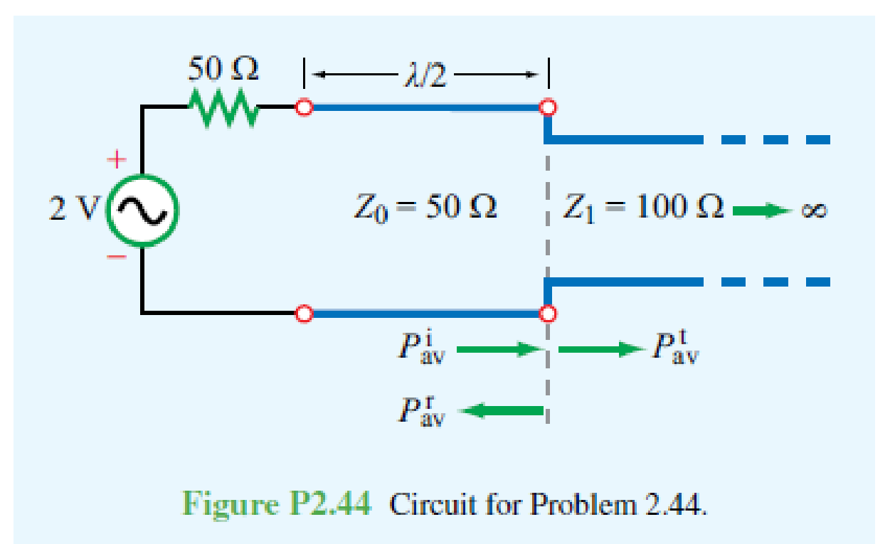
Chapter 2, Problem 44P
For the circuit shown in Fig. P2.44, calculate the average incident power, the average reflected power, and the average power transmitted into the infinite 100 Ω line. The
Expert Solution & Answer
Want to see the full answer?
Check out a sample textbook solution
Students have asked these similar questions
a) A 50 cm length 50 ohms coaxial cable is terminated with an antenna having an impedance of 100 + j150 ohms to be operated at 3.5 GHz. The cable is made with inner and outer conductor and dielectric (relative permittivity = 2.56) in between the two conductors.
(i) Determine the load reflection coefficient.
(ii) Find the standing wave ratio (SWR).
(iii) Determine the input impedance of the line.
(iv) What can you do to reduce the load reflection coefficient?
The antenna in Q.(a) is to be matched to the said 50 Ω coaxial line using single series stub tuner. You are requested to find two solutions using open circuited stub using Smith Chart.
(i) Determine the normalized load impedance and plot on the Smith Chart?
(ii) Find the two possible distance of the stub from the load.
(iii) Find the two possible length of the stub.
(iv) Sketch the circuits
A 350 km transmission line has the following parameters:
z = 0.0195 +j0.35 Ω/km
y = j4.5 μS/km
If the load served by the line is 300 MVA, with an fp of 0.8(-), at a voltage
of 100√3KV say:
6. The value of the incident and reflected wave, as well as the total voltage, at a point 200 km from the end of the
load.
7. The voltage and current at the emitting end.
8. What would be the percentage error in the magnitude of the voltage VS if it is calculated with the lossless line model?
lossless line model? Note that the accurate value is the one that takes losses into account.
A load has a reflection coefficient of 0.5 when referred to 50 Ω. The load is at the end of a line with a 50 Ω characteristic impedance.(a) If the line has an electrical length of 45 degrees, what is the reflection coefficient calculated at the input of the line?(b) What is the VSWR on the 50 Ω line?
Chapter 2 Solutions
Fundamentals of Applied Electromagnetics (7th Edition)
Ch. 2.2 - What is a transmission line? When should...Ch. 2.2 - Prob. 2CQCh. 2.2 - What constitutes a TEM transmission line?Ch. 2.2 - Prob. 4CQCh. 2.2 - Prob. 1ECh. 2.2 - Calculate the transmission line parameters at 1...Ch. 2.4 - Verify that Eq. (2.26a) indeed provides a solution...Ch. 2.4 - A two-wire air line has the following line...Ch. 2.6 - The attenuation constant represents ohmic losses....Ch. 2.6 - How is the wavelength of the wave traveling on...
Ch. 2.6 - Prob. 7CQCh. 2.6 - What is a standing-wave pattern? Why is its period...Ch. 2.6 - Prob. 9CQCh. 2.6 - For a lossless transmission line, = 20.7 cm at 1...Ch. 2.6 - A lossless transmission line uses a dielectric...Ch. 2.6 - Prob. 7ECh. 2.6 - Prob. 8ECh. 2.6 - Prob. 10ECh. 2.6 - A 140 lossless line is terminated in a load...Ch. 2.8 - What is the difference between the characteristic...Ch. 2.8 - What is a quarter-wave transformer? How can it be...Ch. 2.8 - Prob. 12CQCh. 2.8 - Prob. 13CQCh. 2.8 - if the input impedance of a lossless line is...Ch. 2.8 - Prob. 12ECh. 2.8 - A 300 feedline is to be connected to a 3 m long,...Ch. 2.9 - According to Eq. (2.102b), the instantaneous value...Ch. 2.9 - Prob. 16CQCh. 2.9 - What fraction of the incident power is delivered...Ch. 2.9 - Prob. 18CQCh. 2.9 - For a 50 lossless transmission line terminated in...Ch. 2.9 - For the line of Exercise 2-14, what is the...Ch. 2.10 - The outer perimeter of the Smith chart represents...Ch. 2.10 - What is an SWR circle? What quantities are...Ch. 2.10 - What line length corresponds to one complete...Ch. 2.10 - Which points on the SWR circle correspond to...Ch. 2.10 - Prob. 23CQCh. 2.10 - Use the Smith chart to find the values of ...Ch. 2.11 - Prob. 24CQCh. 2.11 - Prob. 25CQCh. 2.12 - What is transient analysis used for?Ch. 2.12 - Prob. 28CQCh. 2.12 - What is the difference between the bounce diagram...Ch. 2 - A transmission line of length l connects a load to...Ch. 2 - Show that the transmission-line model shown in...Ch. 2 - A 1 GHz parallel-plate transmission line consists...Ch. 2 - For the parallel-plate transmission line of...Ch. 2 - In addition to not dissipating power, a lossless...Ch. 2 - For a distortionless line [see Problem 2.13] with...Ch. 2 - Prob. 15PCh. 2 - A transmission line operating at 125 MHz has Z0 =...Ch. 2 - Prob. 17PCh. 2 - Polyethylene with r=2.25 is used as the insulating...Ch. 2 - Prob. 20PCh. 2 - Prob. 21PCh. 2 - Prob. 22PCh. 2 - Prob. 23PCh. 2 - A 50 lossless line terminated in a purely...Ch. 2 - Prob. 26PCh. 2 - Prob. 27PCh. 2 - Prob. 29PCh. 2 - Prob. 30PCh. 2 - Two half-wave dipole antennas, each with an...Ch. 2 - Prob. 34PCh. 2 - For the lossless transmission line circuit shown...Ch. 2 - A lossless transmission line is terminated in a...Ch. 2 - The input impedance of a 31 cm long lossless...Ch. 2 - FM broadcast station uses a 300 transmission line...Ch. 2 - A generator with Vg=300 V and Zg = 50 is...Ch. 2 - If the two-antenna configuration shown in Fig....Ch. 2 - For the circuit shown in Fig. P2.44, calculate the...Ch. 2 - The circuit shown in Fig. P2.45 consists of a 100 ...Ch. 2 - An antenna with a load impedance ZL=(75+j25) is...Ch. 2 - Prob. 47PCh. 2 - Use the Smith chart to determine the input...Ch. 2 - Prob. 52PCh. 2 - A lossless 50 transmission line is terminated in...Ch. 2 - A lossless 50 transmission line is terminated in...Ch. 2 - Use the Smith chart to find yL if zL = 1.5 j0.7.Ch. 2 - Prob. 59PCh. 2 - Prob. 62PCh. 2 - Determine Zin of the feed line shown in Fig....Ch. 2 - Prob. 73PCh. 2 - A 25 antenna is connected to a 75 lossless...Ch. 2 - Prob. 75PCh. 2 - Prob. 76PCh. 2 - Prob. 77PCh. 2 - In response to a step voltage, the voltage...Ch. 2 - Suppose the voltage waveform shown in Fig. P2.77...Ch. 2 - For the circuit of Problem 2.80, generate a bounce...Ch. 2 - In response to a step voltage, the voltage...
Knowledge Booster


Learn more about
Need a deep-dive on the concept behind this application? Look no further. Learn more about this topic, electrical-engineering and related others by exploring similar questions and additional content below.Similar questions
- A 50Ω lossless transmission line is terminated in a load (50+j100) Ω. Using a smith chart, determine the reflection coefficient.arrow_forwardA signal generator having an internal resistance 1 Ω and an open-circuit voltage vg(t) = 0.3 cos 2π 108 t (v) is connected to a 50 Ω lossy transmission line. The line is 4 (m) long, and the velocity of wave propagation on the line is 2.5 x 10⁸ (m/s) with attenuation constant of 0.01 (dB/m). For a matched load, find: (a) The propagation constant on the line. (b) the instantaneous expressions for the voltage and current at an arbitrary location on the line, (c) the instantaneous expressions for the voltage and current at the load, and (d) the average power transmitted to the load.arrow_forwardA 350 km transmission line has the following parameters: z = 0.0195 +j0.35 Ω/km y = j4.5 μS/km If the load served by the line is 300 MVA, with an fp of 0.8(-), at a voltage of 100√3KV say: 6. The value of the incident and reflected wave, as well as the total voltage, at a point 200 km away from the extreme load. 7. The voltage and current at the emitting end. 8. What would be the percentage error in the magnitude of the voltage VS if it is calculated with the lossless line model? lossless line model? Note that the accurate value is the one that takes losses into account.arrow_forward
- 5 (a) With an aid of a simple diagram explain the construction of a coaxial cable (b) If a load of 50 Ohms terminates a transmission line of impedance 100 Ohms calculate the reflectance and the amplitude of the reflected wave (given a unit amplitude incident wave). Also find the VSWR in this case (c) A 50Ω transmission line is connected to an antenna with load impedance of ZL = (25-j50) Ω. Design a short-circuited parallel stub required to match the lines. (Use a smith chart and upload it along with your answers)arrow_forwardQI/ A lossless coaxial cable of 170 mm long has the parameters L 245 nH/m and C 200 pF/m. The operating frequency is f 1GHz and the line is terminated by ZL 100 ome, determine: A) The characteristic impedance .B) The input impedance at the input terminals of the line. C) The standing wave ratio on the line.arrow_forwardA transmitter delivers 50 W into a 600 Ω lossless line that is terminated with an antenna that has an impedance of 275 Ω, resistive. (a) What is the coefficient of reflection? (b) How much of the power actually reaches the antenna?arrow_forward
- For the RG-214 cable listed in Fig. 1.10( c) determine the power loss at 0.1 GHz, when the input power is the maximum rated , for a length o' 5 m.arrow_forward9. Assume a transmission line with ZL = 85 + j45 Ω and Zo = 30 Ω. If the frequency of the line is 1.5GHz, use the Smith Chart to find: i) the reflection coefficient; ii) the distance to the first voltage maximum; iii) the voltage standing wave ratio; iv) the admittance of the load; v) the position of the short-circuited stub on the main line for a perfect impedance matching; vi) the length of the short-circuited stub. (Show all steps on the Smith chart)arrow_forwardAn antenna with a load impedance ZL = (100 + j40)Ω is connected to a transmitter Zg = Z0 through a 75−Ω lossless transmission line. If under matched conditions the transmitter can deliver 15 W to the load, how much power can it deliver to the antenna?arrow_forward
- Antenna connected to a 150- lossless line, produces a standing wave ratio of 2.6. Ifmeasurements indicate that voltage maxima are 120 cm apart and that the last maximum is 40 cmfrom the antenna, calculate:(1) The operating frequency(2) The antenna impedance(3) The reflection coefficient. Assume that the phase velocity = c.arrow_forwardQ1) A 70 cm long lossless transmission line with characteristics impedance of 50 Ω operating at 5Mhz is terminated with a load of ?? = (65+j80) Ω. If the velocity is 0.8 times the velocity of light, then calculate (a) The reflection co-efficient, also verify the value using the given smith chart.(b) Compute the input impedance using the transmission line input impedance equation.arrow_forwardA lossless transmission line has a Zo of 50 ohms and a line velocity of 2.4 x 10^8 m/s. If the operating frequency is 1 MHz. Determine the capacitance in pf.arrow_forward
arrow_back_ios
SEE MORE QUESTIONS
arrow_forward_ios
Recommended textbooks for you
 Introductory Circuit Analysis (13th Edition)Electrical EngineeringISBN:9780133923605Author:Robert L. BoylestadPublisher:PEARSON
 Delmar's Standard Textbook Of ElectricityElectrical EngineeringISBN:9781337900348Author:Stephen L. HermanPublisher:Cengage Learning
 Programmable Logic ControllersElectrical EngineeringISBN:9780073373843Author:Frank D. PetruzellaPublisher:McGraw-Hill Education
 Fundamentals of Electric CircuitsElectrical EngineeringISBN:9780078028229Author:Charles K Alexander, Matthew SadikuPublisher:McGraw-Hill Education
 Electric Circuits. (11th Edition)Electrical EngineeringISBN:9780134746968Author:James W. Nilsson, Susan RiedelPublisher:PEARSON
 Engineering ElectromagneticsElectrical EngineeringISBN:9780078028151Author:Hayt, William H. (william Hart), Jr, BUCK, John A.Publisher:Mcgraw-hill Education,
Introductory Circuit Analysis (13th Edition)
Electrical Engineering
ISBN:9780133923605
Author:Robert L. Boylestad
Publisher:PEARSON
Delmar's Standard Textbook Of Electricity
Electrical Engineering
ISBN:9781337900348
Author:Stephen L. Herman
Publisher:Cengage Learning
Programmable Logic Controllers
Electrical Engineering
ISBN:9780073373843
Author:Frank D. Petruzella
Publisher:McGraw-Hill Education
Fundamentals of Electric Circuits
Electrical Engineering
ISBN:9780078028229
Author:Charles K Alexander, Matthew Sadiku
Publisher:McGraw-Hill Education
Electric Circuits. (11th Edition)
Electrical Engineering
ISBN:9780134746968
Author:James W. Nilsson, Susan Riedel
Publisher:PEARSON
Engineering Electromagnetics
Electrical Engineering
ISBN:9780078028151
Author:Hayt, William H. (william Hart), Jr, BUCK, John A.
Publisher:Mcgraw-hill Education,
How do Electric Transmission Lines Work?; Author: Practical Engineering;https://www.youtube.com/watch?v=qjY31x0m3d8;License: Standard Youtube License