
Videos
The switch S in Figure 20.27 is closed at t = 0 and the current at a reference time tref> 0 is Iref. If the circuit is changed as, described below and the switch is again dosed at t = 0, determine whether the current I at the same time would be greater than, less than, or equal to the original value of Iref. Indicate your answers wilt G. L. or E, respectively. (a) Both the battery voltage ε and the resistance R are doubled. (b) The inductance L b doubled. (c) The battery voltage ε. the resistance R, and the inductance L are each doubled.
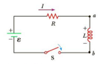
Figure 20.27 A series RL circuit. As the current increases toward its maximum value, the inductor produces an emf that opposes the increasing current.

Trending nowThis is a popular solution!

Chapter 20 Solutions
COLLEGE PHYSICS,V.2


- How long after switch S1 is thrown does it take the current in the circuit shown to reach half its maximum value? Express your answer in terms of the time constant of the circuit.arrow_forwardTwo infinite solenoids cross the plane of the circuit as shown below. The radii of the solenoids are 0.10 and 020 m, respectively, and the current in each solenoid is changing such that dB/dt50.0T/s . What are die currents in die resistors of the circuit?arrow_forwardA steady current flows through a circuit with a large induct3ve time constant. When a switch in the circuit is opened, a large spark across the terminals of the switch. Explain.arrow_forward
- A 120-V, series-wound motor has a field resistance of 80 and an armature resistance of 10. When it is operating at full speed, a back emf of 75 V is generated, (a) What is the initial current drawn by the motor? When the motor is operating at full speed, where are (b) the current drawn by the motor, (c) the power output of the source, [ d) the power output of the motor, and (e) the power dissipated in the two resistances?arrow_forwardDoes the time required for the current in an RL circuit to reach any fraction of its steady-state value depend on the emf of the battery?arrow_forwardConsider the circuit shown in the figure, with =36.0 V,R, =50.02,R=1502 and L= 4.00 H. (a) Switch S, is closed. Just after S. is closed, what are the current i, through R, and the potential differences V and Va ? AC (b) After S. has been closed a long time so that the current has reached its final, steady value, what are i, . VAc and Ve ? (c) Find the expressions for i, , Vac and Ve as functions of time since S, was closed. Do your results agree with what you get in (a) and (b) ? Graph i, . Vsc and Ve as a function oftime. Ro L Aarrow_forward
- ) THE FOLLOWING QUESTIONS ARE BASED ON THE INFORMATION GIVEN HERE. In the circuit shown in the figure, the S switch is closed at t = 0 and the capacitors, which are completely empty, begin to fill. Here E = 45 V, C = 5 µF and R = 100 2. R A) What is the time constant of the circuit, T, in units of microseconds? Answer:arrow_forwardPlease Asaparrow_forwardin the circuit shown in the figure, the S switch is closed at t=0 and the capasitors, which are completely empty, begin to fill. Here E=30V, C=3 uF and R=40 ohm. A) what is the time constant of the circuit, T, in the units of microseconds? B)when t=T, what is the total charge, in units of microcoulomb?arrow_forward
- E and F pleasearrow_forwardGive a proper answer for the following (undrstandable writing )arrow_forwardA Solunoid of radius 1.50cm has 480 turns and a length of 25:0cm a) Find the rate at which current must change!! Through it. to Produce an emt of 60.0 m V₁. (Enter the magnitude), Lind dechrobe i d Note: Answer must be in A/S.arrow_forward

 Glencoe Physics: Principles and Problems, Student...PhysicsISBN:9780078807213Author:Paul W. ZitzewitzPublisher:Glencoe/McGraw-Hill