Loose Leaf For Mechanics Of Materials Format: Looseleaf
7th Edition
ISBN: 9780077625245
Author: BEER
Publisher: Mcgraw Hill Publishers
expand_more
expand_more
format_list_bulleted
Concept explainers
Videos
Textbook Question
Chapter 2.1, Problem 26P
Members ABC and DEF are joined with steel links (E = 200 GPa). Each of the links is made of a pair of 25 × 35-mm plates. Determine the change in length of (a) member BE, (b) member CF.
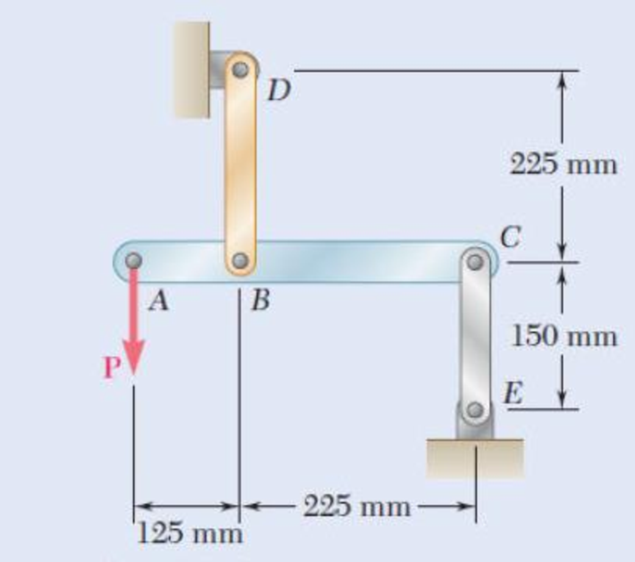
Fig. P2.26
Expert Solution & Answer
Want to see the full answer?
Check out a sample textbook solution
Students have asked these similar questions
The 981-kg uniform bar AB is suspended from two cables AC and BD each with cross-sectional area 339 mm2. Find the location x (in mm) of P that can be safely applied to the bar if the stresses in AC and BD are limited to 119 MPa and 52 MPa, respectively. Express your answer in two decimal places.
The 1021-kg uniform bar AB is suspended from two cables AC and BD each with cross-sectional area 472 mm2. Find the magnitude of P (in N) that can be safely applied to the bar if the stresses in AC and BD are limited to 110 MPa and 51 MPa, respectively. Express your answer in two decimal places.
A fabric used in air-inflated structures is subjected to a biaxial loading that results in normal stresses ox = 18 ksi and oz = 24 ksi.Knowing that the properties of the fabric can be approximated as E = 12.6 x 10 psi and v = 0.34, determine the change in length of (a) side AB, (b) side BC, (c) diagonal AC.
Chapter 2 Solutions
Loose Leaf For Mechanics Of Materials Format: Looseleaf
Ch. 2.1 - A nylon thread is subjected to a 8.5-N tension...Ch. 2.1 - A 4.8-ft-long steel wire of 14 -in.-diameter is...Ch. 2.1 - An 18-m-long steel wire of 5-mm diameter is to be...Ch. 2.1 - Two gage marks are placed exactly 250 mm apart on...Ch. 2.1 - An aluminum pipe must not stretch more than 0.05...Ch. 2.1 - A control rod made of yellow brass must not...Ch. 2.1 - A steel control rod is 5.5 ft long and must not...Ch. 2.1 - A cast-iron tube is used to support a compressive...Ch. 2.1 - A 4-m-long steel rod must not stretch more than 3...Ch. 2.1 - A nylon thread is to be subjected to a 10-N...
Ch. 2.1 - A block of 10-in. length and 1.8 1.6-in. cross...Ch. 2.1 - A square yellow-brass bar must not stretch more...Ch. 2.1 - Rod BD is made of steel (E = 29 106 psi) and is...Ch. 2.1 - The 4-mm-diameter cable BC is made of a steel with...Ch. 2.1 - A single axial load of magnitude P = 15 kips is...Ch. 2.1 - A 250-mm-long aluminum tube (E = 70 GPa) of 36-mm...Ch. 2.1 - The specimen shown has been cut from a...Ch. 2.1 - The brass tube AB (E = 105 GPa) has a...Ch. 2.1 - Both portions of the rod ABC are made of an...Ch. 2.1 - The rod ABC is made of an aluminum for which E =...Ch. 2.1 - For the steel truss (E = 200 GPa) and loading...Ch. 2.1 - For the steel truss (E = 29 106 psi) and loading...Ch. 2.1 - Members AB and BC are made of steel (E = 29 106...Ch. 2.1 - The steel frame (E = 200 GPa) shown has a diagonal...Ch. 2.1 - Link BD is made of brass (E = 105 GPa) and has a...Ch. 2.1 - Members ABC and DEF are joined with steel links (E...Ch. 2.1 - Each of the links AB and CD is made of aluminum (E...Ch. 2.1 - The length of the 332-in.-diameter steel wire CD...Ch. 2.1 - A homogenous cable of length L and uniform cross...Ch. 2.1 - The vertical load P is applied at the center A of...Ch. 2.1 - Denoting by the "engineering strain'' in a...Ch. 2.1 - The volume of a tensile specimen is essentially...Ch. 2.3 - An axial centric force of magnitude P = 450 kN is...Ch. 2.3 - An axial centric force of magnitude P = 450 kN is...Ch. 2.3 - The 4.5-ft concrete post is reinforced with six...Ch. 2.3 - The 4.5-ft concrete post is reinforced with six...Ch. 2.3 - An axial force of 200 kW is applied to the...Ch. 2.3 - The length of the assembly shown decreases by 0.40...Ch. 2.3 - A polystyrene rod consisting of two cylindrical...Ch. 2.3 - Three steel rods (E = 29 106 psi) support an...Ch. 2.3 - Fig. P2.41 2.41 Two cylindrical rods, one of steel...Ch. 2.3 - Solve Prob. 2.41, assuming that rod AC is made of...Ch. 2.3 - Each of the rods BD and CE is made of brass (E =...Ch. 2.3 - The rigid bar AD is supported by two steel wires...Ch. 2.3 - The rigid bar ABC is suspended from three wines of...Ch. 2.3 - The rigid bar AD is supported by two steel wires...Ch. 2.3 - The aluminum shell is fully bonded to the brass...Ch. 2.3 - The aluminum shell is fully bonded to the brass...Ch. 2.3 - The brass shell (b = 11.6 10-6/F) is fully bonded...Ch. 2.3 - The concrete post (Ec = 3.6 106) psi and c = 5.5 ...Ch. 2.3 - A rod consisting of two cylindrical portions AB...Ch. 2.3 - A rod consisting of two cylindrical portions AB...Ch. 2.3 - Fig. P2.52 2.52 A rod consisting of two...Ch. 2.3 - The steel rails of a railroad (rack (Es = 200GPa,...Ch. 2.3 - Two steel bars (Es = 200 GPa and s = 11.7 10-6/C)...Ch. 2.3 - Determine the maximum load P that can be applied...Ch. 2.3 - An aluminum rod (Ea = 70 GPa, a = 23.6 10-6/C)...Ch. 2.3 - Knowing that a 0.02-in. gap exists when the...Ch. 2.3 - Determine (a) the compressive force in the bars...Ch. 2.3 - At room temperature (20C) a 0.5-mm gap exists...Ch. 2.9 - A standard tension test is used to determine the...Ch. 2.9 - A 2-m length of an aluminum pipe of 240-nun outer...Ch. 2.9 - A line of slope 4:10 has been scribed on a...Ch. 2.9 - A 2.75-kN tensile load is applied to a test coupon...Ch. 2.9 - Fig. P2.65 2.65 In a standard tensile test a steel...Ch. 2.9 - The change in diameter of a large steel bolt is...Ch. 2.9 - The brass rod AD is fitted with a jacket that is...Ch. 2.9 - A fabric used in air-inflated structures is...Ch. 2.9 - A 1-in. square was scribed on the side of a large...Ch. 2.9 - The block shown is made of a magnesium alloy for...Ch. 2.9 - The homogeneous plate ABCD is subjected to a...Ch. 2.9 - For a member under axial loading, express the...Ch. 2.9 - In many situations it is known that the normal...Ch. 2.9 - In many situations physical constraints prevent...Ch. 2.9 - The plastic block shown is bonded to a rigid...Ch. 2.9 - The plastic block shown is bonded to a rigid...Ch. 2.9 - Two blocks of rubber with a modulus of rigidity G...Ch. 2.9 - Fig. P2.77 and P2.78 2.78 Two blocks of rubber...Ch. 2.9 - An elastomeric bearing (G = 130 psi) is used to...Ch. 2.9 - 2.80 For the elastomeric bearing In Prob. 2.79...Ch. 2.9 - A vibration isolation unit consists of two blocks...Ch. 2.9 - Prob. 82PCh. 2.9 - Prob. 83PCh. 2.9 - Prob. 84PCh. 2.9 - Prob. 85PCh. 2.9 - A 2.75-kN tensile load is applied to a test coupon...Ch. 2.9 - A vibration isolation support consists of a rod A...Ch. 2.9 - Prob. 88PCh. 2.9 - Prob. 89PCh. 2.9 - Show that for any given material, the ratio G/E of...Ch. 2.9 - Prob. 91PCh. 2.9 - Prob. 92PCh. 2.13 - Knowing that, for the plate shown, the allowable...Ch. 2.13 - Knowing that P = 38 kN, determine the maximum...Ch. 2.13 - A hole is to be drilled in the plate at A. The...Ch. 2.13 - Fig. P2.95 and P2.96 2.96 (a) For P = 13 kips and...Ch. 2.13 - 2.97 Knowing that the hole has a diameter of 9 mm,...Ch. 2.13 - For P = 100 kN, determine the minimum plate...Ch. 2.13 - Prob. 99PCh. 2.13 - A centric axial force is applied to the steel bar...Ch. 2.13 - The cylindrical rod AB has a length L = 5 ft and a...Ch. 2.13 - Fig. P2.101 and P.102 2.102 The cylindrical rod AB...Ch. 2.13 - Rod AB is made of a mild steel that is assumed to...Ch. 2.13 - Prob. 104PCh. 2.13 - Rod ABC consists of two cylindrical portions and...Ch. 2.13 - Prob. 106PCh. 2.13 - Prob. 107PCh. 2.13 - Prob. 108PCh. 2.13 - Each cable has a cross-sectional area of 100 mm2...Ch. 2.13 - Prob. 110PCh. 2.13 - Two tempered-steel bars, each 316 in. thick, are...Ch. 2.13 - Prob. 112PCh. 2.13 - Prob. 113PCh. 2.13 - Prob. 114PCh. 2.13 - Prob. 115PCh. 2.13 - Prob. 116PCh. 2.13 - Prob. 117PCh. 2.13 - Prob. 118PCh. 2.13 - Prob. 119PCh. 2.13 - For the composite bar in Prob. 2.111, determine...Ch. 2.13 - Prob. 121PCh. 2.13 - Bar AB has a cross-sectional area of 1200 mm2 and...Ch. 2.13 - Bar AB has a cross-sectional area of 1200 mm2 and...Ch. 2 - The uniform wire ABC, of unstretched length 2l, is...Ch. 2 - The aluminum rod ABC (E = 10.1 106 psi), which...Ch. 2 - Two solid cylindrical rods are joined at B and...Ch. 2 - Prob. 127RPCh. 2 - Prob. 128RPCh. 2 - Prob. 129RPCh. 2 - A 4-ft concrete post is reinforced with four steel...Ch. 2 - The steel rods BE and CD each have a 16-mm...Ch. 2 - Prob. 132RPCh. 2 - Prob. 133RPCh. 2 - The aluminum test specimen shown is subjected to...Ch. 2 - Prob. 135RP
Knowledge Booster


Learn more about
Need a deep-dive on the concept behind this application? Look no further. Learn more about this topic, mechanical-engineering and related others by exploring similar questions and additional content below.Similar questions
- Each of the three aluminum bars shown is to be twisted through an angle of 2.1°. Knowing that b = 30 mm, τall = 50 MPa, and G = 27 GPa, determine the shortest allowable length of each bar. Refer to Table 3.1. The shortest allowable length of bar (a) is mm. The shortest allowable length of bar (b) is mm. The shortest allowable length of bar (c) is mm.arrow_forwardTwo cylindrical rods, one of steel and the other of brass, are joined at C and restrained by rigid supports at A and E. The steel rod has a length of 300 mm while the brass rod has a length of 200 mm. The diameters of the rods are shown in the figure below. A force of 60 kN is applied at point B of the steel segment. For the loading shown and knowing that modulus of elasticity values for steel and brass are respectively Es = 200 GPa and Eb = 105 GPa, determine a.) The reactions at A and E: RA and RE. b.) The deflection of point C from its original location. how to doarrow_forwardA 16-mm-diameter steel [E= 200 GPa] rod (2) is connected to a 50-mm-wide by 8-mm-thick rectangular aluminum [E= 70 GPa] bar (1). Determine the force Prequired to stretch the assembly 3.00 mm.arrow_forward
- The block shown is made of a magnesium alloy for which E = 45 GPa and ν= 0.35. Knowing that σx=–180 MPa, determine (a) the magnitude of σy for which the change in the height of the block will be zero, (b) the corresponding change in the area of the face ABCD, (c) the corresponding change in the volume of the blockarrow_forwardIn a standard tensile test, a steel rod of 22-mm diameter is subjected to a tension force of 75 kN. Knowing that ν=0.30 and E=200 GPa, determine (a) the elongation of the rod in a 200-mm gage length, (b) the change in diameter of the rodarrow_forwardA fabric used in air-inflated structures is subjected to a biaxial load-ing that results in normal stresses σx=120 MPa and σz =160 MPa. Knowing that the properties of the fabric can be approximated as E=87 GPa and ν= 0.34, determine the change in length of (a) side AB, (b) side BC, (c) diagonal AC.arrow_forward
- A steel rod is subjected to a gradually applied load (F) which gave a rise to a maximum stress of 200 MPa. The rod is 250 mm long and one part of its length is square and the remainder is circular with a diameter of 25 mm. If the total strain energy in the rod and modulus elasticity of the material is 1.3 J and 200 GPa, determine the following:1.The applied load F2.The total extension of the bar3.The length of the square portion of the bar4.The suddenly applied load that will induce the same amount of energy 5.The load that falls from a height of 8 mm induces 1,3 J in the bar.arrow_forwardA 5-kN tensile load will be applied to a 50-m length of steel wire with E = 200 GPa. Determine the smallest diameter wire that can be used, knowing that the normal stress must not exceed 150 MPa and that the increase in length of the wire must not exceed 25 mm.arrow_forwardThe truss shown is subjected to forces P = 68 kN, the length L divided equally, and H = 0.6 m. If the resistance of bar 1 is 151 kN; Determine the maximum length (in meters) of the reinforcement so that the resistance of said bar is not exceeded.arrow_forward
- Two forces P1 and P2, with a magnitude of P1 = 15 kN and P2 = 18 kN, are applied as shown in Figure below to the end A of bar AB, which is welded to a cylindrical member BD of radius c = 20 mm. Knowing that the distance from A to the axis of member BD is a = 50 mm and assuming that all stresses remain below the proportional limit of the material, determine the normal and shearing stresses at points H and K of the transverse section of member BD located at a distance b = 60 mm from end B,arrow_forward6. A strain gage located at C on the surface of bone AB indicates that the average normal stress in the bone is 3.80 MPa when the bone is subjected to two 1200-N forces as shown. Assuming the cross section of the bone at C to be annular and knowing that its outer diameter is 25 mm, determine the inner diameter of the bone’s cross section at C.arrow_forwardThe brass tube AB (E= 105 GPa) has a cross-sectional area of 14 0 m m2 and is fitted with a plug at A. The tube is attached at B to a rigid plate that is itself attached at C to the bottom of an alumi-num cylinder (E= 72 GPa) with a cross-sectional area of 250 mm2. The cylinder is then hung from a support at D. In order to close the cylinder, the plug must move down through 1 mm. Determine the force P that must be applied to the cylinder.arrow_forward
arrow_back_ios
SEE MORE QUESTIONS
arrow_forward_ios
Recommended textbooks for you
 Elements Of ElectromagneticsMechanical EngineeringISBN:9780190698614Author:Sadiku, Matthew N. O.Publisher:Oxford University Press
 Mechanics of Materials (10th Edition)Mechanical EngineeringISBN:9780134319650Author:Russell C. HibbelerPublisher:PEARSON
 Thermodynamics: An Engineering ApproachMechanical EngineeringISBN:9781259822674Author:Yunus A. Cengel Dr., Michael A. BolesPublisher:McGraw-Hill Education
 Control Systems EngineeringMechanical EngineeringISBN:9781118170519Author:Norman S. NisePublisher:WILEY
 Mechanics of Materials (MindTap Course List)Mechanical EngineeringISBN:9781337093347Author:Barry J. Goodno, James M. GerePublisher:Cengage Learning
 Engineering Mechanics: StaticsMechanical EngineeringISBN:9781118807330Author:James L. Meriam, L. G. Kraige, J. N. BoltonPublisher:WILEY
Elements Of Electromagnetics
Mechanical Engineering
ISBN:9780190698614
Author:Sadiku, Matthew N. O.
Publisher:Oxford University Press
Mechanics of Materials (10th Edition)
Mechanical Engineering
ISBN:9780134319650
Author:Russell C. Hibbeler
Publisher:PEARSON
Thermodynamics: An Engineering Approach
Mechanical Engineering
ISBN:9781259822674
Author:Yunus A. Cengel Dr., Michael A. Boles
Publisher:McGraw-Hill Education
Control Systems Engineering
Mechanical Engineering
ISBN:9781118170519
Author:Norman S. Nise
Publisher:WILEY
Mechanics of Materials (MindTap Course List)
Mechanical Engineering
ISBN:9781337093347
Author:Barry J. Goodno, James M. Gere
Publisher:Cengage Learning
Engineering Mechanics: Statics
Mechanical Engineering
ISBN:9781118807330
Author:James L. Meriam, L. G. Kraige, J. N. Bolton
Publisher:WILEY
EVERYTHING on Axial Loading Normal Stress in 10 MINUTES - Mechanics of Materials; Author: Less Boring Lectures;https://www.youtube.com/watch?v=jQ-fNqZWrNg;License: Standard YouTube License, CC-BY