
Concept explainers
Videos
Two steel bars (Es = 200 GPa and αs = 11.7 × 10⁻⁶/°C) are used to reinforce a brass bar (Eb =105 GPa, αb = 20.9 × 10⁻⁶/°C) that is subjected to a load P = 25 kN. When the steel bars were fabricated; the distance between the centers of the holes that were to fit on the pins was made 0.5 mm smaller than the 2 m needed. The steel bars were then placed in an oven to increase their length so that they would just fit on the pins. Following fabrication, the temperature in the steel bars dropped back to room temperature. Determine (a) the increase in temperature that was required to fit the steel bars on the pins, (b) the stress in the brass bar after the load is applied to it.
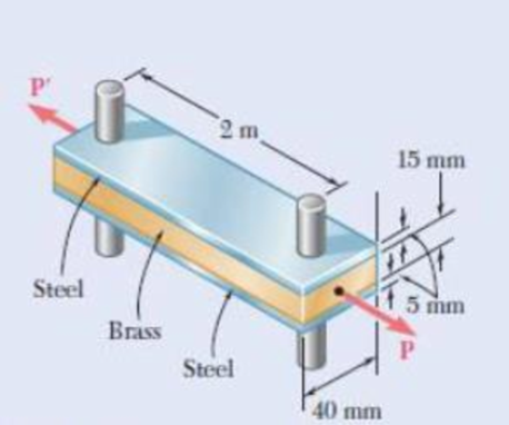
Fig. P2.55
(a)
The required temperature increment to fit the steel bars on the pins.
Answer to Problem 55P
The required temperature increment to fit the steel bars on the pins is
Explanation of Solution
Given information:
The magnitude of load
The coefficient
The coefficient
The young’s modulus
The young’s modulus
Determine the temperature change require to expand steel bar by this amount.
Here,
Substitute
Thus, the required temperature increment to fit the steel bars on the pins is
(b)
The normal stress in the brass bar after load applied.
Answer to Problem 55P
The normal stress due to steel is
The normal stress due to brass is
Explanation of Solution
Calculation:
After the assembly of the bars, a compressive force is developed in the brass bars and a tensile force is developed in the steel bars.
Determine the area
Here, b is the width of the steel bar , d is the depth of the steel bar, and t is the thickness of the bar.
Substitute
Determine the deformation of steel
Here, F is the compressive force, L is the length of the bar, and
Substitute
Determine the area
Here, b is the width of the brass bar, d is the depth of the brass bar.
Substitute
Determine the deformation of brass
Here,
Substitute
The deformation of bar and steel is equal to the initial amount of misfit.
Here,
Substitute
Find the stresses due to fabrication for steel using the relation:
Substitute
Find the stresses due to fabrication for brass using the relation:
Substitute
The stresses should be added the stress due to the
Consider
Find the force developed in steel bar
Substitute
Find the force developed in brass bar
Substitute
Find the force P as follows:
Here,
Substitute
Substitute
Substitute
Find the normal stress
Substitute
Find the normal stress
Substitute
The stress due to fabrication added.
Find the total stress using the relation:
Here,
Substitute
Thus, the normal stress due to steel is
Find the total stress using the relation:
Substitute
Thus, the normal stress due to brass is
Want to see more full solutions like this?
Chapter 2 Solutions
Loose Leaf For Mechanics Of Materials Format: Looseleaf


- A copper bar consists from three sections: sections 1 is of 25 mm diameter and 60 mm long, section 2 is of 15 mm diameter and 50 mm long and section 3 is 20 mm square and 40 mm long. The bar is subjected to an axial tensile load which induces a stress of 20 MN/m2 on the smallest cross section. Determine the total Increase in the length of the bar when the load is applied. For copper E=100 GN/m2.arrow_forwardA steel rod is subjected to a gradually applied load (F) which gave a rise to a maximum stress of 200 MPa. The rod is 250 mm long and one part of its length is square and the remainder is circular with a diameter of 25 mm. If the total strain energy in the rod and modulus elasticity of the material is 1.3 J and 200 GPa, determine the following:1.The applied load F2.The total extension of the bar3.The length of the square portion of the bar4.The suddenly applied load that will induce the same amount of energy 5.The load that falls from a height of 8 mm induces 1,3 J in the bar.arrow_forwardA solid aluminum [E = 64 GPa] rod (1) is connected to a solid bronze [E = 114 GPa] rod (2) at flange B, as shown. Aluminum rod (1) has an outside diameter of 36 mm and bronze rod (2) has an outside diameter of 17 mm. The normal stress in the aluminum rod must be limited to 124 MPa, and the normal stress in the bronze rod must be limited to 92 MPa. Assume L1 = 168 mm and L2 = 399 mm. Determine: (a) the maximum downward load P that may be applied at flange B. (Answer: P = 146kN)(b) the deflection vB (downward is positive) of flange B at the load determined in part(a). (Answer: vB = .322 mm)arrow_forward
- The load of 2000 lb is to be supported by the two vertical steel wires for which sY = 70 ksi. Originally wire AB is 60 in. long and wire AC is 60.04 in. long. Determine the cross-sectional area of AB if the load is to be shared equally between both wires. Wire AC has a cross-sectional area of 0.02 in2. Est = 29.0(103) ksi.arrow_forwardA steel bar of 40 mm x 40 mm square cross section is subjected to an axial compressive load of 200 kN. If the length of the bar is 2 m and E = 200 GPa, the contraction of the bar will be, (a) 1.25 mm, (b) 2.70 mm (c) 4.05 mm (d) 5 40 mmarrow_forwardA railroad track is laid at a temperature of 15°F with gaps of 0.01 feet between the ends of the rails. The rails are 33 feet long. If they are prevented from buckling, what stress will result from a temperature of 110°F? ( 6.5 x 10° per deg F) (Answer 9,450 Psi)arrow_forward
- A pulley is supported by a circular pin at A. The pin has a diameter of d = 0.375 in., and each side of the pulley support bracket has a thickness of t = 0.1250 in. The average shear stress in the pin cannot exceed 50 ksi, and the bearing stress in the pulley support bracket cannot exceed 70 ksi. Determine the maximum value of Pmax that can be supported by the assembly.arrow_forwarda 12mm thick steel tire has a width of 110mm and an internal diameter of 800mm. It is heated and shrunk onto a steel wheel 800.50mm in diameter. The modulus of elasticity of steel is 200gpa. Which of the following most nearly gives the comprehensive pressure between the tire and the wheel? A 3.30 mpa B 3.90 mpa C 3.75 mpa D 4.35 mpaarrow_forwardThe pipe assembly shown is subjected to a force F = 7 kN and P = 14 kN. It is made of steel with Sy = 250 MPa. Determine the safety factor at point H using the maximum shear stress theory. Select one: a. NH = 6.427 b. NH = 3.570 c. NH = 5.355 d. NH = 4.590arrow_forward
- The assembly shown below consists of a brass shell (1) fully bonded to a ceramic core (2). The brass shell [E = 115 GPa; α = 18.7 x 10⁻⁶ /°C] has an outside diameter of 50 mm and an inside diameter of 35 mm. The ceramic core [E = 290 GPa; α = 3.1 x 10⁻⁶ /°C] has a diameter of 35 mm. At a temperature of 15°C, the assembly is unstressed. Determine the largest temperature increase that is acceptable for the assembly if the normal stress in the longitudinal direction of the brass shell must not exceed 80 MPa.arrow_forwardA) A circular rod with a gage length of 3.6 m and a diameter of 2.3 cm is subjected to an axial load of 51 kN . If the modulus of elasticity is 200 GPa , what is the change in length? B)A circular rod with a length of 4 m and a diameter of 2.4 cm is subjected to an axial load of 61 kN . If the resulting change in length is 3.34 mm , what is the modulus of elasticity? C)A circular rod with a length of 3.7 m and a diameter of 2.7 cm is subjected to an axial load and increases in length by 3.26 mm . The initial portion of the stress-strain curve of the material is given. What is the applied load?arrow_forwardTHe bracket shown is made of cold drawn steel with Sy=400MPa and Su=480 MPa, and is fastened to a beam made of the same material by five rivets that are made of a steel with Sy=300 MPa and Sut=365 MPa. The thickness of the bracket and the beam are 12 mm and 16 mm respectively.Diameters of the rivets are 20 mm. What safe load F(steady) can be supported by the riveted joint for a factor of safety of 2. Use distortion energy theory of failure.arrow_forward
 Elements Of ElectromagneticsMechanical EngineeringISBN:9780190698614Author:Sadiku, Matthew N. O.Publisher:Oxford University Press
 Mechanics of Materials (10th Edition)Mechanical EngineeringISBN:9780134319650Author:Russell C. HibbelerPublisher:PEARSON
 Thermodynamics: An Engineering ApproachMechanical EngineeringISBN:9781259822674Author:Yunus A. Cengel Dr., Michael A. BolesPublisher:McGraw-Hill Education
 Control Systems EngineeringMechanical EngineeringISBN:9781118170519Author:Norman S. NisePublisher:WILEY
 Mechanics of Materials (MindTap Course List)Mechanical EngineeringISBN:9781337093347Author:Barry J. Goodno, James M. GerePublisher:Cengage Learning
 Engineering Mechanics: StaticsMechanical EngineeringISBN:9781118807330Author:James L. Meriam, L. G. Kraige, J. N. BoltonPublisher:WILEY