Concept explainers
Videos
(a)
Find the maximum deflection at point C of the cylindrical portions.
(a)
Answer to Problem 107P
The maximum deflection at point C of the cylindrical portions is
Explanation of Solution
Given information:
The cross sectional area AC and BC of each portions is
The modulus of elasticity (E) for portion AC is
The yield stress
The modulus of elasticity (E) for portion CB is
The yield stress
Calculation:
Calculate the displacement at point C to cause yielding of AC using the relation:
Here,
Substitute
Find the corresponding force along AC using the relation as follows:
Substitute
Find the corresponding force along CB using the relation as follows:
Substitute
Sketch the element C as shown in Figure 1.
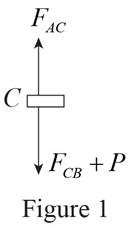
Refer to Figure 1.
Find the value of P using equilibrium element.
Substitute
Since the applied load,
Refer to Figure 1.
Find the force along CB as follows:
Substitute
Determine the deflection at point C using the relation:
Substitute
Thus, the maximum deflection at point C of the cylindrical portions is
(b)
Find the maximum stress for each portion of rod.
(b)
Answer to Problem 107P
The maximum stress of rod AC is
The maximum stress of rod BC is
Explanation of Solution
Calculation:
Refer part a.
The maximum stress of rod AC is
Therefore, the maximum stress of rod AC is
Determine the maximum stress at point BC using the relation:
Substitute
Thus, the maximum stress of rod BC is
(c)
Find the permanent deflection at point C.
(c)
Answer to Problem 107P
The permanent deflection at point C is
Explanation of Solution
Write the expression of deflection and force for unloading as follows:
The value of
Substitute
Determine the deflection using the relation.
Substitute
Find the permanent deflection using the relation:
Substitute
Thus, the permanent deflection at point C is
Want to see more full solutions like this?
Chapter 2 Solutions
Loose Leaf For Mechanics Of Materials Format: Looseleaf


- A steel rod is subjected to a gradually applied load (F) which gave a rise to a maximum stress of 200 MPa. The rod is 250 mm long and one part of its length is square and the remainder is circular with a diameter of 25 mm. If the total strain energy in the rod and modulus elasticity of the material is 1.3 J and 200 GPa, determine the following:1.The applied load F2.The total extension of the bar3.The length of the square portion of the bar4.The suddenly applied load that will induce the same amount of energy 5.The load that falls from a height of 8 mm induces 1,3 J in the bar.arrow_forwardA column with the cross section shown has a 13.5-ft effective length. Using a factor of safety equal to 2.8, determine the allowable centric load that can be applied to the column. Use E= 29 x106 psi.arrow_forwardA straight girder of uniform section and length L rests on supports at the ends, and is propped up by a third support in the middle. The weight of the girder and its load is w per unit length. If the central support does not yield, prove that it takes a load equal to (5/8)wL. ANSWER: 1.80cm and 2.48cm Please show solution to the answer.arrow_forward
- Rigid bar ABC is supported by bronze rod (1) and aluminum rod (2), as shown. A concentrated load P is applied to the free end of aluminum rod (3). Bronze rod (1) has an elastic modulus of E1 = 15,000 ksi and a diameter of d1 = 0.50 in. Aluminum rod (2) has an elastic modulus of E2 = 10,000 ksi and a diameter of d2 = 0.85in. Aluminum rod (3) has a diameter of d3 = 1.00in. The yield strength of the bronze is 48 ksi and the yield strength of the aluminum is 40 ksi. Assume a = 2.5 ft, b = 1.5 ft, L1 = 6 ft, L2 = 8 ft, and L3 = 3 ft. (A) Calculate the cross-sectional areas of the three rods. in in.2 (B) For a factor of safety of 2.1, calculate the allowable stresses in the bronze and the aluminum rods. IN KSI. (C) What is the magnitude of load P that can safely be applied to the structure for a minimum factor of safety of 2.1? in kips (D) The pin used at B has an ultimate shear strength of 58 ksi. If a factor of safety of 2.5 is required, determine the allowable shear stress in this pin.…arrow_forwardRigid bar ABC is supported by bronze rod (1) and aluminum rod (2), as shown. A concentrated load P is applied to the free end of aluminum rod (3). Bronze rod (1) has an elastic modulus of E1 = 15,000 ksi and a diameter of d1 = 0.40 in. Aluminum rod (2) has an elastic modulus of E2 = 10,000 ksi and a diameter of d2 = 0.70in. Aluminum rod (3) has a diameter of d3 = 1.00in. The yield strength of the bronze is 48 ksi and the yield strength of the aluminum is 40 ksi. Assume a = 2.5 ft, b = 1.5 ft, L1 = 6 ft, L2 = 8 ft, and L3 = 3 ft.arrow_forwardThe cylindrical bar composed of two parts (AB and BC) is fixed at ends A and C. The two parts are made of different materials with different cross-sections. An external load ? =28 kN is applied at point B. The cross-sectional area of AB and BC part is 0.9 cm2and 0.3 cm2, respectively. The modulus of elasticity of the AB and BC part is 40 GPa and 200 GPa, respectively. Determine the force reactions at ends A and C.arrow_forward
- A stainless steel tube with an outside diameter of 50 mm and a wall thickness of 5 mm is used as a compression member. If the axial stress in the member must be limited to 384 MPa, determine the maximum load P that the member can support.arrow_forwardA 10-mm diameter steel bolt is surrounded by bronze sleeve. The outer diameter of the bronze sleeve is 20 mm and its inner diameter is 10-mm. Given that the yield stress for the steel is 640 MPa and the yield stress for the bronze is 520 MPa, determine the magnitude of the maximum allowable total load that can be applied to this assembly. (Assume full bond between the steel and the bronze sleeve) Esteel = 200 GPa, Ebronze = 100 GPa, Factor of safety = 1.5arrow_forwardA copper bar consists from three sections: sections 1 is of 25 mm diameter and 60 mm long, section 2 is of 15 mm diameter and 50 mm long and section 3 is 20 mm square and 40 mm long. The bar is subjected to an axial tensile load which induces a stress of 20 MN/m2 on the smallest cross section. Determine the total Increase in the length of the bar when the load is applied. For copper E=100 GN/m2.arrow_forward
- A 2-m length of an aluminum pipe of 240-mm outer diameter and 10-mm wall thickness is used as a short column to carry a 640-kN centric axial load. Knowing that E= 73 GPa and ν=0.33, determine (a) the change in length of the pipe, (b) the change in its outer diam-eter, (c) the change in its wall thicknessarrow_forwardThe 70-mm-diameter steel rod ABC, and a brass rod CD of the same diameter, are joined at point C to form the 7.5-m long rod “ABCD”. E’s for the materials in the rod are shown in the picture below. For the loading shown, and neglecting the weight of the rod, determine: a) the deflection of point B b) the deflection of point C c) the deflection of point D d) the longitudinal stress in the middle of section AB e) the longitudinal stress in the middle of section BC f) the longitudinal stress in the middle of section CD a) all elemental stiffness matrices, b) the force matrix, and the c) assembly stiffness matrixarrow_forwardTHe bracket shown is made of cold drawn steel with Sy=400MPa and Su=480 MPa, and is fastened to a beam made of the same material by five rivets that are made of a steel with Sy=300 MPa and Sut=365 MPa. The thickness of the bracket and the beam are 12 mm and 16 mm respectively.Diameters of the rivets are 20 mm. What safe load F(steady) can be supported by the riveted joint for a factor of safety of 2. Use distortion energy theory of failure.arrow_forward
 Elements Of ElectromagneticsMechanical EngineeringISBN:9780190698614Author:Sadiku, Matthew N. O.Publisher:Oxford University Press
 Mechanics of Materials (10th Edition)Mechanical EngineeringISBN:9780134319650Author:Russell C. HibbelerPublisher:PEARSON
 Thermodynamics: An Engineering ApproachMechanical EngineeringISBN:9781259822674Author:Yunus A. Cengel Dr., Michael A. BolesPublisher:McGraw-Hill Education
 Control Systems EngineeringMechanical EngineeringISBN:9781118170519Author:Norman S. NisePublisher:WILEY
 Mechanics of Materials (MindTap Course List)Mechanical EngineeringISBN:9781337093347Author:Barry J. Goodno, James M. GerePublisher:Cengage Learning
 Engineering Mechanics: StaticsMechanical EngineeringISBN:9781118807330Author:James L. Meriam, L. G. Kraige, J. N. BoltonPublisher:WILEY