Understanding Motor Controls
3rd Edition
ISBN: 9781305498129
Author: Stephen L. Herman
Publisher: Cengage Learning
expand_more
expand_more
format_list_bulleted
Concept explainers
Videos
Textbook Question
Chapter 22, Problem 6RQ
Refer to the circuit shown in Figure 22–1. Should float switch FS2 be wired as normally open or normally closed? Explain your answer.
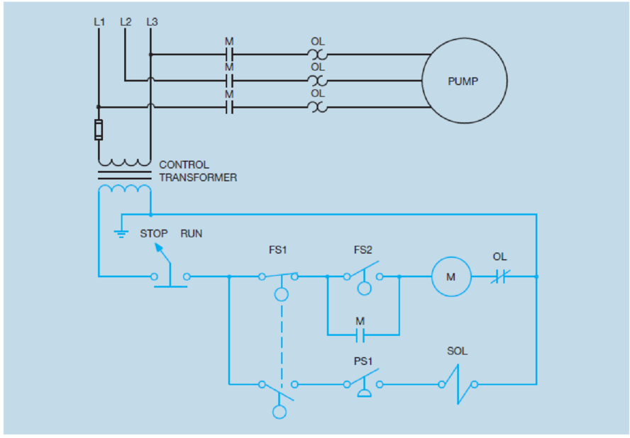
Figure 22–1 Pump control circuit.
Expert Solution & Answer
Want to see the full answer?
Check out a sample textbook solution
Students have asked these similar questions
Draw and Explain the Circuit diagram for holding the cylinder of double acting cylinder in the fully extended position using 4/3 dc valve?
Chapter 22 Solutions
Understanding Motor Controls
Ch. 22 - Prob. 1RQCh. 22 - When connecting a control system, what should be...Ch. 22 - What should be done to each component to help...Ch. 22 - What is the disadvantage of wiring components to a...Ch. 22 - What is the main advantage of making connections...Ch. 22 - Refer to the circuit shown in Figure 221. Should...Ch. 22 - What does the dashed line between the two float...
Knowledge Booster


Learn more about
Need a deep-dive on the concept behind this application? Look no further. Learn more about this topic, mechanical-engineering and related others by exploring similar questions and additional content below.Similar questions
- Refer to Figure 21–1 to answer the following questions. In what position must switch SW 123 be set to make connection between terminals 3 and 4?arrow_forwardReferring to the circuit in Figure 2–33, should the float switch be connected as a normally open or normally closed switch?arrow_forwardExplain the difference between cumulative- and differential-compounded connections.arrow_forward
- Refer to Figure 211 to answer the following questions. Referring to switch (RS SW 123), in what position must the switch be set to make connection between terminals 3 and 4?arrow_forwardRefer to the circuit shown in Figure 5-29. Is the thermostat contact normally open, normally closed, normally closed held open, or normally open held closed? Figure 5-29 The contactor contains both load and auxiliary contacts.arrow_forwardRefer to the circuit shown in Figure 33–6. You are to install this control system. How many auxiliary contacts should starter 1L contain and how many are normally open and how many are normally closed?arrow_forward
- Refer to the circuit shown in Figure 16-11. Assume that the platform is located on the bottom floor. When the UP push button is pressed the pump motor does not start. Which of the following could not cause this problem? The contacts of limit switch LS1 are open. The contacts of limit switch LS2 are open. Motor starter coil M is open. The overload contact is open.arrow_forwardRefer to the circuit shown in Figure 16-11. Assume that the platform is located on the lower floor. When the UP push button is pressed, the platform rises. When the platform reaches the upper floor, however, the pump does not turn off but continues to run until the overload relay opens the overload contacts. Which of the following could cause this problem? a. The solenoid valve opened when limit switch LS1 opened. b. The UP push button is shorted. c. Limit switch LS1 did not open its contacts. d. Limit switch LS2 contacts did not reclose when the platform began to rise.arrow_forwardRefer to the circuit shown in Figure 15-6. If an overload should occur on the compressor motor and the overload contact open, would it affect the operation of the lube oil pump?arrow_forward
- To answer the following questions refer to the circuit shown in Figure 41–14. Assume that contact TS1 closes and the air injection blower motor starts operating, but the high-pressure pump motor does not start. What could cause this problem? Temperature switch TS3 is open. Coil 2M is open. Flow switch FL1 is defective and did not close. Coil TR is open.arrow_forwardTo answer the following questions refer to the circuit in Figure 416. The pressure switch is shown as: a. Normally open b. Normally closed c. Normally open held closed d. Normally closed held openarrow_forwardRefer to the circuit shown in Figure 108. In this circuit, the jog button has been connected incorrectly. The normally closed section has been connected in parallel with the run push button and the normally open section has been connected in series with the holding contacts. Explain how this circuit operates.arrow_forward
arrow_back_ios
SEE MORE QUESTIONS
arrow_forward_ios
Recommended textbooks for you
 Understanding Motor ControlsMechanical EngineeringISBN:9781337798686Author:Stephen L. HermanPublisher:Delmar Cengage Learning
 Electrical Transformers and Rotating MachinesMechanical EngineeringISBN:9781305494817Author:Stephen L. HermanPublisher:Cengage Learning
 Refrigeration and Air Conditioning Technology (Mi...Mechanical EngineeringISBN:9781305578296Author:John Tomczyk, Eugene Silberstein, Bill Whitman, Bill JohnsonPublisher:Cengage Learning
 Automotive Technology: A Systems Approach (MindTa...Mechanical EngineeringISBN:9781133612315Author:Jack Erjavec, Rob ThompsonPublisher:Cengage Learning
Understanding Motor Controls
Mechanical Engineering
ISBN:9781337798686
Author:Stephen L. Herman
Publisher:Delmar Cengage Learning
Electrical Transformers and Rotating Machines
Mechanical Engineering
ISBN:9781305494817
Author:Stephen L. Herman
Publisher:Cengage Learning
Refrigeration and Air Conditioning Technology (Mi...
Mechanical Engineering
ISBN:9781305578296
Author:John Tomczyk, Eugene Silberstein, Bill Whitman, Bill Johnson
Publisher:Cengage Learning
Automotive Technology: A Systems Approach (MindTa...
Mechanical Engineering
ISBN:9781133612315
Author:Jack Erjavec, Rob Thompson
Publisher:Cengage Learning
Fluid Mechanics - Viscosity and Shear Strain Rate in 9 Minutes!; Author: Less Boring Lectures;https://www.youtube.com/watch?v=_0aaRDAdPTY;License: Standard youtube license