Concept explainers
Videos
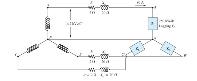
For the Y-Y system of Fig. 24.46 the impedance of each line is
a. Find the total load loss of the system including the line loss.
b. Find the phase voltage of the supply.
c. Find the power factor of the load (including the line loss) on the supply.
d. Is the power factor leading or lagging?
e. Find the magnitude and phase angle of each phase of the balanced load.
f. Find the power factor of the load (not including the line loss).
Want to see the full answer?
Check out a sample textbook solution
Chapter 24 Solutions
EBK INTRODUCTORY CIRCUIT ANALYSIS


- Consider a three-phase Y-connected source feeding a balanced- load. The phasor sum of the line currents as well as the neutral current are always zero. (a) True (b) Falsearrow_forwardA three-phase generator in Y is connected to a balanced three-phase load in Δ of Z= 2.24∠26.57° Ω. If Van = 120∠30° and Vbn = 120∠150°, determine the line voltages and currents.arrow_forwardSuppose you are Mr. Y who is working as an assistant engineer of PGCB. You have studied a wye-wye system during your investigation of a three-phase system. In this system, a Y-connected balanced three-phase generator is connected to a Y- connected balanced load with an impedance of 24 + j19 ohm per phase. The line joining the generator and the load has an impedance of 0.6 + j0.7 ohm per phase. Assuming a positive sequence for the source voltages and that Van = Xarrow_forward
- A three-phase transmission line has resistance and inductive reactance of 25V and 90V, respectively. With no load at the receiving end, a synchronous compensator there takes a current lagging by 90; the voltage is 145 kV at the sending end and 132 kV at the receiving end. Calculate the value of the current taken by the compensator. When the load at the receiving end is 50MW, it is found that the line can operate with unchanged voltages at the sending and receiving ends, provided that the compensator takes the same current as before, but now leading by 90. Calculate the reactive power of the loadarrow_forward1. a) Find the reading of each wattmeter in the circuit shown if ZA=20 30° Ω, ZB=60 0° Ω, and ZC=40 −30° Ω. 2. b) Show that the sum of the wattmeter readings equals the total average power delivered to the unbalanced three-phase load.arrow_forwardQ6: i) Which of the following is true for a transmission line under load? Power factor at both the sending and receiving end will be equal Reactive Power at both the sending and receiving end will be equal. Active Power at the sending end will be greater than the active power at the receiving end. Line current in the sending end will be equal to the line current at the receiving end ii) A transmission line has 80% efficiency when delivering 500 KW power to a 3-phase load at the receiving end. This implies that ______. Voltage regulation of the line is 20% Active power at the receiving side 375 kw/phase Active power at the sending end is 500 kw/phase Total power loss in the transmission line is 125 kW iii) Which of the following is true for transmission line under no-load? Power factor at the sending end will be unity Active Power at the…arrow_forward
- A balanced delta connected generator supplies a line voltage of 180v rms to a balanced load connected in w and e, with a sequence abc and having an angle of 0 ° for the voltage Vab. considering that the load per phase is 45 + 20j Ω, calculate all the line currents and the real power (w) supplied by this generator to the loadarrow_forwardConsider the configuration from Problem 1, except that each phase of the transmission line has an impedance of ݆1.5 Ω. a. Determine the line currents. b. Determine the line‐neutral voltage for each branch of the 3Φ load. c. Determine the complex power consumed by the 3Φ load. d. Determine the complex power produced by the 3Φ source. e. Determine the power consumed by the transmission line. f. Determine the load power factor, and the power factor observed by the source. problem 1 : Each leg of a symmetric, Y‐connected, 3Φ load has an impedance of 10∠36.87° Ω, and is connected to A 60 Hz, balanced, positive‐sequence, Y‐connected 3Φ voltage source with Vrms .3Φ source via an ideal transmission line (that is, the connection from the source to the load has zero impedance).arrow_forwardA balanced Y-connected load is connected to 3-phase transmission lines with line-to-line voltages of 21.5 kV. The current in each line is 75 A. What are the phase impedances of the Y-connected load?arrow_forward
- Ibc find the load current Vca find the line voltage Calculate the complex power on the transmission linearrow_forwardProblem 2A three-phase generator in Y is connected to a balanced three-phase load in Δ of Z = 2.24∠26.57 ° Ω. If Van = 120∠30 ° and Vbn = 120∠150 °, determine the line voltages and currents.arrow_forward1) A short three-phase transmission line has a per-phase series impedance of 0 . 53 ∠ 55 . 20 Ω. The line supplies the three-phase load at the receiving end of 825 kW at 0.8 power factor lagging. If the line-to-line sending end voltage is 3.4 kV, using short line model determine: (a) the receiving-end line-to-line voltage in kV and determine percent voltage drop across the line; (b) the line current; (c) the sending-end power factorarrow_forward
 Power System Analysis and Design (MindTap Course ...Electrical EngineeringISBN:9781305632134Author:J. Duncan Glover, Thomas Overbye, Mulukutla S. SarmaPublisher:Cengage Learning