EBK INTRODUCTORY CIRCUIT ANALYSIS
13th Edition
ISBN: 8220100668234
Author: Boylestad
Publisher: PEARSON
expand_more
expand_more
format_list_bulleted
Concept explainers
Videos
Textbook Question
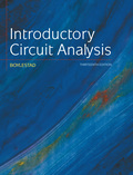
Chapter 24, Problem 43P
Find the total watts, volt-amperes reactive, volt-amperes, and Fp of the sytem in Fig. 24.52.
Expert Solution & Answer
Want to see the full answer?
Check out a sample textbook solution
Students have asked these similar questions
Find phase difference of power supply voltage and vR(wich is equal to angle of current)
In table 1
Please help me with this problem...
Question:
For the three-phase, a three-wire system of Fig. 22.52, find the magnitude of the current through each phase of the load and find the total watts, volt-amperes reactive, volt-amperes, and Fp of the load.
Three conductors of a 3-phase overhead line are arranged in a horizontal plane 6 m apart. The diameter of each conductor is 1·24 cm. Find the capacitance of each conductor to neutral per 100 km of the line.
Chapter 24 Solutions
EBK INTRODUCTORY CIRCUIT ANALYSIS
Ch. 24 - A balanced V load having a 10 resistance in each...Ch. 24 - Repeat Problem 1 if each phase impedance is...Ch. 24 - Repeat Problem 1 if each phase impedance is...Ch. 24 - The phase sequence for the Y-Y system in Fig....Ch. 24 - Repeat Problem 4 if each phase impedance are...Ch. 24 - Repeat Problem 4 if each phase impedance is...Ch. 24 - For the system in Fig. 24.43, find the magnitude...Ch. 24 - Computer the magnitude of the voltage EAB for the...Ch. 24 - For the Y-Y system in Fig. 24.45: a. Find the...Ch. 24 - For the Y-Y system of Fig. 24.46 the impedance of...
Ch. 24 - A balanced load having a 20 resistance in each...Ch. 24 - Repeat Problem 11 if each phase impedance is...Ch. 24 - Repeat Problem 11 if each phase impedance is...Ch. 24 - The phase sequence for the Y- system in Fig....Ch. 24 - Repeat Problem 14 if each phase impedance is...Ch. 24 - Repeat Problem 14 if each phase impedance are...Ch. 24 - Prob. 17PCh. 24 - For the connected load in Fig. 24.49: a. Find the...Ch. 24 - A balanced V load having a 30 resistance in each...Ch. 24 - Repeat Problem 19 if each phase impedance is...Ch. 24 - Prob. 21PCh. 24 - Prob. 22PCh. 24 - Prob. 23PCh. 24 - Repeat Problem 22 if each phase impedance is...Ch. 24 - Prob. 25PCh. 24 - Prob. 26PCh. 24 - Prob. 27PCh. 24 - The phase sequence for the - system in Fig....Ch. 24 - Repeat Problem 28 if each phase impedance is...Ch. 24 - Repeat Problem 28 if each phase impedance is...Ch. 24 - Prob. 31PCh. 24 - Prob. 32PCh. 24 - Prob. 33PCh. 24 - Find the total watts, volt-amperes reactive,...Ch. 24 - Prob. 35PCh. 24 - Find the total watts, volt-amperes reactive,...Ch. 24 - Find the total watts, volt-amperes reactive,...Ch. 24 - Prob. 38PCh. 24 - Prob. 39PCh. 24 - Find the total watts, volt-amperes reactive,...Ch. 24 - A balanced, three-phase, -connected load has a...Ch. 24 - A balanced, three-phase, Y-connected load has a...Ch. 24 - Find the total watts, volt-amperes reactive,...Ch. 24 - The Y-Y system in Fig. 24.53 has a balanced load...Ch. 24 - Prob. 45PCh. 24 - Prob. 46PCh. 24 - Repeat Problem 46 for the network in Fig. 24.47.Ch. 24 - For the three-wire system in Fig. 24.55, properly...Ch. 24 - Sketch three different ways that two wattmeters...Ch. 24 - For the Y- system in Fig. 24.56: Determine the...Ch. 24 - For the system in Fig. 24.57: Calculate the...Ch. 24 - For the three-phase, three-wire system in Fig....
Knowledge Booster


Learn more about
Need a deep-dive on the concept behind this application? Look no further. Learn more about this topic, electrical-engineering and related others by exploring similar questions and additional content below.Similar questions
- A single phase transmission line is transmitting power to a load of 1,100 KW at 11 KV and at unity power fector. If it has a total resistance of 5 Ω, what is the efficiency of the transmission line? :arrow_forwardThree conductors of a 3-phase overhead line are arranged in a horizontal plane 6 m apart. The diameter of each conductor is 1·24 cm. Find the capacitance of each conductor to neutral per 100 km of the line. [0·785 μF]arrow_forwardA three phase transmission line to line capacitive reactance value is 12 ohms. If the charging current of a line per phase is 37 A. Choose the corresponding phase voltage from the values given below. 21.07V 0.32V 444.00V 256.34Varrow_forward
- A No.10 AWG aluminum conductor carrying a load of 16A on a 220 V, single-phase circuit. Approximate the maximum distance. Use a maximum voltage drop of 3%. (Hint: the conductor has a cross-sectional area of 10, 380 cmils)arrow_forwardDerive the relationship between in case of star and delta connected load between: a). Phase voltage and line voltage b). Phase current and line currentarrow_forwardA single phase transmission line is transmitting 1,100 KW power at 11 KV and at unity power fector. If it has a total resistance of 5 Ω, what is the efficiency of the transmission line?arrow_forward
- A single phase transmission line has two parallel conductors 1.5 meters apart with 2.5cm diameter. The Loop inductance is:arrow_forwardA transmitter sends a 5W of power to a 75 ohm line. Suppose the transmitter and the line is matched but the load is not. Determine the power absorbed by the load if the coefficient of reflection is 0.75.arrow_forwarda single-phase transmission line has two parallel conductors, 1.5 meters apart. the radius of each conductor is 0.3 cm. calculate the inductance per meter of the line.arrow_forward
- For an AC source of 0.4V calculate node voltage V in rectangular and polar form?arrow_forward2.5 cm in a 200 km long transmission line. Three diameter line conductors are arranged in a horizontal formation. The line has been transposed. Find the inductance per phase and the capacitance per phase if there is a distance of 3 meters between two adjacent wires.arrow_forwardFind the phase differences between voltages and currents.arrow_forward
arrow_back_ios
SEE MORE QUESTIONS
arrow_forward_ios
Recommended textbooks for you
 Introductory Circuit Analysis (13th Edition)Electrical EngineeringISBN:9780133923605Author:Robert L. BoylestadPublisher:PEARSON
 Delmar's Standard Textbook Of ElectricityElectrical EngineeringISBN:9781337900348Author:Stephen L. HermanPublisher:Cengage Learning
 Programmable Logic ControllersElectrical EngineeringISBN:9780073373843Author:Frank D. PetruzellaPublisher:McGraw-Hill Education
 Fundamentals of Electric CircuitsElectrical EngineeringISBN:9780078028229Author:Charles K Alexander, Matthew SadikuPublisher:McGraw-Hill Education
 Electric Circuits. (11th Edition)Electrical EngineeringISBN:9780134746968Author:James W. Nilsson, Susan RiedelPublisher:PEARSON
 Engineering ElectromagneticsElectrical EngineeringISBN:9780078028151Author:Hayt, William H. (william Hart), Jr, BUCK, John A.Publisher:Mcgraw-hill Education,
Introductory Circuit Analysis (13th Edition)
Electrical Engineering
ISBN:9780133923605
Author:Robert L. Boylestad
Publisher:PEARSON
Delmar's Standard Textbook Of Electricity
Electrical Engineering
ISBN:9781337900348
Author:Stephen L. Herman
Publisher:Cengage Learning
Programmable Logic Controllers
Electrical Engineering
ISBN:9780073373843
Author:Frank D. Petruzella
Publisher:McGraw-Hill Education
Fundamentals of Electric Circuits
Electrical Engineering
ISBN:9780078028229
Author:Charles K Alexander, Matthew Sadiku
Publisher:McGraw-Hill Education
Electric Circuits. (11th Edition)
Electrical Engineering
ISBN:9780134746968
Author:James W. Nilsson, Susan Riedel
Publisher:PEARSON
Engineering Electromagnetics
Electrical Engineering
ISBN:9780078028151
Author:Hayt, William H. (william Hart), Jr, BUCK, John A.
Publisher:Mcgraw-hill Education,
Z Parameters - Impedance Parameters; Author: Electrical Engineering Authority;https://www.youtube.com/watch?v=qoD4AoNmySA;License: Standard Youtube License