
Fundamentals Of Physics - Volume 1 Only
11th Edition
ISBN: 9781119306856
Author: Halliday
Publisher: WILEY
expand_more
expand_more
format_list_bulleted
Concept explainers
Videos
Textbook Question
Chapter 25, Problem 19P
GO In Fig. 25-34, the battery has potential difference V = 9.0 V, C2 = 3.0 μF, C4 = 4.0 μF, and all the capacitors are initially uncharged. When switch S is closed, a total charge of 12 μC passes through point aand a total charge of 8.0 μC passes through point b. What are (a) C1 and (b) C3?
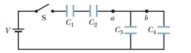
Figure 25-34 Problem 19.
Expert Solution & Answer
Want to see the full answer?
Check out a sample textbook solution
Students have asked these similar questions
In the figure the battery has potential difference V = 14.0 V, C2 = 3.70 μF, C4 = 4.10 μF, and all the capacitors are initially uncharged. When switch S is closed, a total charge of 14.0 μC passes through point a and a total charge of 7.00 μC passes through point b. What are (a) C1 and (b) C3?
A capacitor is made up of two long coaxial cylindrical conductorsseparated by a vaccum. If the capacitance per unit length is 97.0 pF/m,the ratio of the radii of the outer cylinder and the inner cylinder is mostnearly
In the circuit C1=3.00 uF, C2 = 5.00 uF, C3=6.00 uF, the potential difference given that Vab = +24.0 V. count a) dash on body and dash on each body b) difference across individual capacitors c) potential difference between points a and d
Chapter 25 Solutions
Fundamentals Of Physics - Volume 1 Only
Ch. 25 - Figure 25-18 shows plots of charge versus...Ch. 25 - What is Ceq of three capacitors, each of...Ch. 25 - a In Fig. 25-19a are capacitors 1 and 3 in series?...Ch. 25 - Figure 25-20 shows three circuits, each consisting...Ch. 25 - Initially, a single capacitance C1 is wired to a...Ch. 25 - Repeat Question 5 for C2 added in series rather...Ch. 25 - For each circuit in Fig. 25-21, are the capacitors...Ch. 25 - Figure 25-22 shows an open switch, a battery of...Ch. 25 - A parallel-plate capacitor is connected to a...Ch. 25 - When a dielectric slab is inserted between the...
Ch. 25 - You are to connect capacitances C1 and C2, with...Ch. 25 - The two metal objects in Fig. 25-24 have net...Ch. 25 - The capacitor in Fig. 25-25 has a capacitance of...Ch. 25 - SSM A parallel-plate capacitor has circular plates...Ch. 25 - The plates of spherical capacitor have radii 38.0...Ch. 25 - What is the capacitance of a drop that results...Ch. 25 - You have two flat metal plates, each of area...Ch. 25 - If an uncharged parallel-plate capacitor...Ch. 25 - How many 1.00 F capacitors must be connected in...Ch. 25 - Each of the uncharged capacitors in Fig. 25-27 has...Ch. 25 - In Fig. 25-28, find the equivalent capacitance of...Ch. 25 - In Fig. 25-29, find the equivalent capacitance of...Ch. 25 - Two parallel-plate capacitors, 6.0 F each, are...Ch. 25 - SSM ILW A 100 pF capacitor is charged to a...Ch. 25 - GO In Fig. 25-30, the battery has a potential...Ch. 25 - GO In Fig. 25-31, a 20.0 V battery is connected...Ch. 25 - Plot in Fig. 25-32a gives the charge q that can be...Ch. 25 - GO In Fig. 25-29, a potential difference of V =...Ch. 25 - Figure 25-33 shows a circuit section of four...Ch. 25 - GO In Fig. 25-34, the battery has potential...Ch. 25 - Figure 25-35 shows a variable "airgap capacitor...Ch. 25 - SSM WWWIn Fig. 25-36, capacitances are charged C1...Ch. 25 - In Fig. 25-37, V = 10 V, C1 = 10 F, and C2 = C3 =...Ch. 25 - The capacitors in Fig. 25-38 are initially...Ch. 25 - GO Figure 25-39 represents two air-filled...Ch. 25 - GO In Fig. 25-40, two parallel-plate capacitors...Ch. 25 - GO Capacitor 3 in Fig. 25-41a is a variable...Ch. 25 - GO Figure 25-42 shows a 12.0 V battery and four...Ch. 25 - GO Figure 25-43 displays a 12.0 V battery and 3...Ch. 25 - What capacitance is required to store an energy of...Ch. 25 - How much energy is stored in 1.00 m3of air due to...Ch. 25 - SSMA 2.0 F capacitor and a 4.0 F capacitor are...Ch. 25 - A parallel-plate air-filled capacitor having area...Ch. 25 - A charged isolated metal sphere of diameter 10 cm...Ch. 25 - In Fig. 25-28, a potential difference V = 100 V is...Ch. 25 - Assume that a stationary electron is a point of...Ch. 25 - As a safety engineer, you must evaluate the...Ch. 25 - SSM ILW WWW The parallel plates in a capacitor,...Ch. 25 - In Fig. 25-29, a potential difference V = 100 V is...Ch. 25 - Go In Fig. 25-45, C1 = 10.0 F, C2= 20.0 F, and C3...Ch. 25 - An air-filled parallel-plate capacitor has a...Ch. 25 - SSMA coaxial cable used in a transmission line has...Ch. 25 - A parallel-plate air-filled capacitor has a...Ch. 25 - Given a 7.4 pF air-filled capacitor, you are asked...Ch. 25 - You are asked to construct a capacitor having a...Ch. 25 - A certain parallel-plate capacitor is filled with...Ch. 25 - In Fig. 25-46, how much charge is stored on the...Ch. 25 - SSM ILWA certain substance has a dielectric...Ch. 25 - Figure 25-47 shows a parallel-plate capacitor with...Ch. 25 - Figure 25-48 shows a parallel-plate capacitor with...Ch. 25 - Go Figure 25-49 shows a parallel-plate capacitor...Ch. 25 - SSM WWWA parallel-plate capacitor has a...Ch. 25 - For the arrangement of Fig. 25-17, suppose that...Ch. 25 - A parallel-plate capacitor has plates of area 0.12...Ch. 25 - Two parallel plates of area 100 cm2 are given...Ch. 25 - The space between two concentric conducting...Ch. 25 - In Fig. 25-50, the battery potential difference V...Ch. 25 - SSMIn Fig. 25-51, V = 9.0 V, C1 = C2= 30 F, and C3...Ch. 25 - a If C = 50 F in Fig. 25-52, what is the...Ch. 25 - In Fig.25-53, V = 12 V, C1 = C4 = 2.0 F, C2 = 4.0...Ch. 25 - The chocolate crumb mystery. This troy begins with...Ch. 25 - Figure 25-54 shows capacitor 1 C1 = 8.00 F,...Ch. 25 - Two air-filled, parallel-plate capacitors are to...Ch. 25 - Two parallel-plate capacitors, 6.0 F each, are...Ch. 25 - GO In Fig. 25-55, V = 12 V, C1 = C5 = C6 = 6.0 F,...Ch. 25 - SSM In Fig.25-56, the parallel-plate capacitor of...Ch. 25 - A cylindrical capacitor has radii a and b as in...Ch. 25 - A capacitor of capacitance C1 = 6.00 F is...Ch. 25 - Repeat Problem 67 for the same two capacitors but...Ch. 25 - A certain capacitor is charged to a potential...Ch. 25 - Aslab of copper of thickness b = 2.00 mm is thrust...Ch. 25 - Repeat Problem 70, assuming that a potential...Ch. 25 - A potential difference of 300 V is applied to a...Ch. 25 - Figure 25-58 shows a four capacitor arrangement...Ch. 25 - You have two plates of copper, a sheet of mica...Ch. 25 - A capacitor of unknown capacitance Cis charged to...Ch. 25 - A 10 V battery is connected to a series of n...Ch. 25 - SSM In Fig. 25-59, two parallel-plate capacitors A...Ch. 25 - You have many 2.0F capacitors, each capable of...Ch. 25 - A parallel-plate capacitor has charge q and plate...Ch. 25 - A capacitor is charged until its stored energy is...
Additional Science Textbook Solutions
Find more solutions based on key concepts
As shown below, if M=6.0kg, what is the tension in the connecting string? The pulley and all surfaces are frict...
University Physics Volume 1
If you travel in a straight line at 50 km/h for 1 h and at 100 km/h for another hour, is your average velocity ...
Essential University Physics: Volume 1 (3rd Edition)
Two students are discussing their answer to the previous question.
Student 1: Since the spaceprobe is exactly h...
Lecture- Tutorials for Introductory Astronomy
A radio wave has a frequency of 600,000 Hz and travels at a speed of?
Glencoe Physical Science 2012 Student Edition (Glencoe Science) (McGraw-Hill Education)
35. The basic metric unit of length is ______.
Applied Physics (11th Edition)
Determine the phase of water at a. T260°C.P5MPa b. T=2C,P=100kPa
Fundamentals Of Thermodynamics
Knowledge Booster


Learn more about
Need a deep-dive on the concept behind this application? Look no further. Learn more about this topic, physics and related others by exploring similar questions and additional content below.Similar questions
- According to UE=12C(V)2 (Eq. 27.3), a greater capacitance means more energy is stored by the capacitor, but according to UE = Q2/2C (Eq. 27.2), a greater capacitance means less energy is stored. How can both of these equations be correct?arrow_forwardCalculate the equivalent capacitance for two capacitors (C1: 97.9 nF and C2: 98.5 nF )when they areconnected in (1) parallel and (2) in series.arrow_forwardTwo capacitors are connected in parallel with a switch between them and are fully charged (C1 = 4.00 µF, q1 = 6.00 µC; C2 = 6.00 µF, q2 = 12.0 µC). The switch is closed, and charge flows until equilibrium is reestablished (i.e., until both capacitors have the same voltage across their plates). What is the resulting voltage across either capacitor?arrow_forward
- Two air-filled, parallel-plate capacitors are to be connected to a 10 V battery, first individually, then in series, and then in parallel. In those arrangements, the energy stored in the capacitors turns out to be, listed least to greatest: 225 μJ, 300 μJ, 900 μJ, and 1200 μJ. Of the two capacitors, what is the (a) smaller and (b) greater capacitance?arrow_forwardIn the given network, each capacitor has C = 4.00 μF and Vab = 28.0 V. Calculate the a. Total capacitance b. Charge on each capacitor c. Potential difference on each capacitorarrow_forwardIn the figure to the right, the battery has potential difference V = 9.0 V, C2 = 3.0 uF, and C4 = 4.0 uF. All the capacitors are initially uncharged. When switch S is closed, a total charge of 12.0 uC passes through point a, and a total charge of 8.0 uC passes through point b. Find C1 and C3.arrow_forward
- Two capacitors C1 = 2.2 ?F and C2 = 1.2 ?F, and are connected in parallel to a 24V source as shown in Fig. a. After they are charged they are disconnected from the source and from each other, and then reconnected directly to each other with plates of opposite sign connected together (see Fig. b). Find the charge on each capacitor and the potential across each after equilibrium is established (Fig. c).arrow_forwarda potential difference of V = 85.1 V is applied across a capacitor arrangement with capacitances C1 = 10.3 μF, C2 = 5.37 μF, and C3 = 3.75 μF. If capacitor 3 undergoes electrical breakdown so that it becomes equivalent to conducting wire, what is the increase in (a) the charge on capacitor 1 and (b) the potential difference across capacitor 1?arrow_forwardKINDLY ANSWR IMMEDIATELY, THANKYOU FOR HELPING OUT Three capacitors, each of capacitance 120 picofarad, each are charged to 0.50 kV and then connected in series. Determine a) the potential difference between the end plates, b) the charge on each capacitor, and c) the energy stored in the system. CHOICES; A. 1.5 kV, 60 nanocoulomb, 45 microjoule B. 5.1 kV, 45 microcoulomb, 60 millijoule C. 51 V, 60 millicoulomb, 45 kilojoule D. 15 V, 45 picocoulomb, 60 megajoulearrow_forward
- The image shows a network of capacitors between terminal A and B, with C1=5.00 microfarads, C2=10.0 microfarads, and C3=2.00 microfarads. If the potential difference between points A and B is 60.0-Volt, What charge is stored by C3?arrow_forwardThe figure below shows capacitors 1 (C1=8.00muF), capacitor2 (C2=6.00 muF), and capacitor 3 (C3=8.00 muF) connected to 12V battery. When switch S is closed so as to connect uncharged capacitor 4 (C4=6.00muF) (a) How much charge passes through point P from the battery? (b) How much charge shows up on capacitor 4? (c) How much energy is stored in C1?arrow_forwardThe distance between the plates of a 5.60 μF, parallel-plate air terminal was 5.70 mm and the capacitor was loaded with a potential difference of 420 V. Find the energy density in J/m3 in the region between the plates.arrow_forward
arrow_back_ios
arrow_forward_ios
Recommended textbooks for you
 Physics for Scientists and Engineers, Technology ...PhysicsISBN:9781305116399Author:Raymond A. Serway, John W. JewettPublisher:Cengage Learning
 Physics for Scientists and Engineers: Foundations...PhysicsISBN:9781133939146Author:Katz, Debora M.Publisher:Cengage Learning
Physics for Scientists and Engineers, Technology ...
Physics
ISBN:9781305116399
Author:Raymond A. Serway, John W. Jewett
Publisher:Cengage Learning
Physics for Scientists and Engineers: Foundations...
Physics
ISBN:9781133939146
Author:Katz, Debora M.
Publisher:Cengage Learning
Physics Capacitor & Capacitance part 7 (Parallel Plate capacitor) CBSE class 12; Author: LearnoHub - Class 11, 12;https://www.youtube.com/watch?v=JoW6UstbZ7Y;License: Standard YouTube License, CC-BY