
Fundamentals Of Physics - Volume 1 Only
11th Edition
ISBN: 9781119306856
Author: Halliday
Publisher: WILEY
expand_more
expand_more
format_list_bulleted
Concept explainers
Videos
Textbook Question
Chapter 25, Problem 4Q
Figure 25-20 shows three circuits, each consisting of a switch and two capacitors, initially charged as indicated (top plate positive). After the switches have been closed, in which circuit (if any) will the charge on the left-hand capacitor (a) increase, (b) decrease, and (c) remain the same?
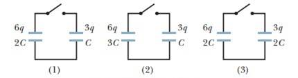
Figure 25-20 Question 4.
Expert Solution & Answer
Want to see the full answer?
Check out a sample textbook solution
Students have asked these similar questions
A capacitor is made up of two long coaxial cylindrical conductorsseparated by a vaccum. If the capacitance per unit length is 97.0 pF/m,the ratio of the radii of the outer cylinder and the inner cylinder is mostnearly
Two capacitors are connected in parallel with a switch between them and are fully charged (C1 = 4.00 µF, q1 = 6.00 µC; C2 = 6.00 µF, q2 = 12.0 µC). The switch is closed, and charge flows until equilibrium is reestablished (i.e., until both capacitors have the same voltage across their plates). What is the resulting voltage across either capacitor?
Two capacitors, empty inside, and with a capacitance of 2μF, are arranged in parallel and connected to an emf of 9V, reaching electrostatic balance without disconnecting the emf, and a dielectric (k=2.5) is introduced that occupies the entire capacitor. . Determine, for the capacitor that was left empty, the change in electric charge (ΔQ), the stored energy, the magnitude of the electric field vector and the energy density. The distance of the plates is 2.5mm.
Chapter 25 Solutions
Fundamentals Of Physics - Volume 1 Only
Ch. 25 - Figure 25-18 shows plots of charge versus...Ch. 25 - What is Ceq of three capacitors, each of...Ch. 25 - a In Fig. 25-19a are capacitors 1 and 3 in series?...Ch. 25 - Figure 25-20 shows three circuits, each consisting...Ch. 25 - Initially, a single capacitance C1 is wired to a...Ch. 25 - Repeat Question 5 for C2 added in series rather...Ch. 25 - For each circuit in Fig. 25-21, are the capacitors...Ch. 25 - Figure 25-22 shows an open switch, a battery of...Ch. 25 - A parallel-plate capacitor is connected to a...Ch. 25 - When a dielectric slab is inserted between the...
Ch. 25 - You are to connect capacitances C1 and C2, with...Ch. 25 - The two metal objects in Fig. 25-24 have net...Ch. 25 - The capacitor in Fig. 25-25 has a capacitance of...Ch. 25 - SSM A parallel-plate capacitor has circular plates...Ch. 25 - The plates of spherical capacitor have radii 38.0...Ch. 25 - What is the capacitance of a drop that results...Ch. 25 - You have two flat metal plates, each of area...Ch. 25 - If an uncharged parallel-plate capacitor...Ch. 25 - How many 1.00 F capacitors must be connected in...Ch. 25 - Each of the uncharged capacitors in Fig. 25-27 has...Ch. 25 - In Fig. 25-28, find the equivalent capacitance of...Ch. 25 - In Fig. 25-29, find the equivalent capacitance of...Ch. 25 - Two parallel-plate capacitors, 6.0 F each, are...Ch. 25 - SSM ILW A 100 pF capacitor is charged to a...Ch. 25 - GO In Fig. 25-30, the battery has a potential...Ch. 25 - GO In Fig. 25-31, a 20.0 V battery is connected...Ch. 25 - Plot in Fig. 25-32a gives the charge q that can be...Ch. 25 - GO In Fig. 25-29, a potential difference of V =...Ch. 25 - Figure 25-33 shows a circuit section of four...Ch. 25 - GO In Fig. 25-34, the battery has potential...Ch. 25 - Figure 25-35 shows a variable "airgap capacitor...Ch. 25 - SSM WWWIn Fig. 25-36, capacitances are charged C1...Ch. 25 - In Fig. 25-37, V = 10 V, C1 = 10 F, and C2 = C3 =...Ch. 25 - The capacitors in Fig. 25-38 are initially...Ch. 25 - GO Figure 25-39 represents two air-filled...Ch. 25 - GO In Fig. 25-40, two parallel-plate capacitors...Ch. 25 - GO Capacitor 3 in Fig. 25-41a is a variable...Ch. 25 - GO Figure 25-42 shows a 12.0 V battery and four...Ch. 25 - GO Figure 25-43 displays a 12.0 V battery and 3...Ch. 25 - What capacitance is required to store an energy of...Ch. 25 - How much energy is stored in 1.00 m3of air due to...Ch. 25 - SSMA 2.0 F capacitor and a 4.0 F capacitor are...Ch. 25 - A parallel-plate air-filled capacitor having area...Ch. 25 - A charged isolated metal sphere of diameter 10 cm...Ch. 25 - In Fig. 25-28, a potential difference V = 100 V is...Ch. 25 - Assume that a stationary electron is a point of...Ch. 25 - As a safety engineer, you must evaluate the...Ch. 25 - SSM ILW WWW The parallel plates in a capacitor,...Ch. 25 - In Fig. 25-29, a potential difference V = 100 V is...Ch. 25 - Go In Fig. 25-45, C1 = 10.0 F, C2= 20.0 F, and C3...Ch. 25 - An air-filled parallel-plate capacitor has a...Ch. 25 - SSMA coaxial cable used in a transmission line has...Ch. 25 - A parallel-plate air-filled capacitor has a...Ch. 25 - Given a 7.4 pF air-filled capacitor, you are asked...Ch. 25 - You are asked to construct a capacitor having a...Ch. 25 - A certain parallel-plate capacitor is filled with...Ch. 25 - In Fig. 25-46, how much charge is stored on the...Ch. 25 - SSM ILWA certain substance has a dielectric...Ch. 25 - Figure 25-47 shows a parallel-plate capacitor with...Ch. 25 - Figure 25-48 shows a parallel-plate capacitor with...Ch. 25 - Go Figure 25-49 shows a parallel-plate capacitor...Ch. 25 - SSM WWWA parallel-plate capacitor has a...Ch. 25 - For the arrangement of Fig. 25-17, suppose that...Ch. 25 - A parallel-plate capacitor has plates of area 0.12...Ch. 25 - Two parallel plates of area 100 cm2 are given...Ch. 25 - The space between two concentric conducting...Ch. 25 - In Fig. 25-50, the battery potential difference V...Ch. 25 - SSMIn Fig. 25-51, V = 9.0 V, C1 = C2= 30 F, and C3...Ch. 25 - a If C = 50 F in Fig. 25-52, what is the...Ch. 25 - In Fig.25-53, V = 12 V, C1 = C4 = 2.0 F, C2 = 4.0...Ch. 25 - The chocolate crumb mystery. This troy begins with...Ch. 25 - Figure 25-54 shows capacitor 1 C1 = 8.00 F,...Ch. 25 - Two air-filled, parallel-plate capacitors are to...Ch. 25 - Two parallel-plate capacitors, 6.0 F each, are...Ch. 25 - GO In Fig. 25-55, V = 12 V, C1 = C5 = C6 = 6.0 F,...Ch. 25 - SSM In Fig.25-56, the parallel-plate capacitor of...Ch. 25 - A cylindrical capacitor has radii a and b as in...Ch. 25 - A capacitor of capacitance C1 = 6.00 F is...Ch. 25 - Repeat Problem 67 for the same two capacitors but...Ch. 25 - A certain capacitor is charged to a potential...Ch. 25 - Aslab of copper of thickness b = 2.00 mm is thrust...Ch. 25 - Repeat Problem 70, assuming that a potential...Ch. 25 - A potential difference of 300 V is applied to a...Ch. 25 - Figure 25-58 shows a four capacitor arrangement...Ch. 25 - You have two plates of copper, a sheet of mica...Ch. 25 - A capacitor of unknown capacitance Cis charged to...Ch. 25 - A 10 V battery is connected to a series of n...Ch. 25 - SSM In Fig. 25-59, two parallel-plate capacitors A...Ch. 25 - You have many 2.0F capacitors, each capable of...Ch. 25 - A parallel-plate capacitor has charge q and plate...Ch. 25 - A capacitor is charged until its stored energy is...
Additional Science Textbook Solutions
Find more solutions based on key concepts
82. How does basaltic lava in a rift zone separate two landmasses?
Conceptual Physical Science (6th Edition)
The pV-diagram of the Carnot cycle.
Sears And Zemansky's University Physics With Modern Physics
A sphere of radius R carries a nonuniform but spherically symmetric volume charge density that results in an el...
Essential University Physics (3rd Edition)
34.102 DATA In setting up an experiment for a high school biology lab, you use a concave spherical mirror to pr...
University Physics (14th Edition)
14. A tall Styrofoam cup is filled with water. Two holes are punched in the cup near the bottom, and water begi...
Physics: Principles with Applications
Knowledge Booster


Learn more about
Need a deep-dive on the concept behind this application? Look no further. Learn more about this topic, physics and related others by exploring similar questions and additional content below.Similar questions
- According to UE=12C(V)2 (Eq. 27.3), a greater capacitance means more energy is stored by the capacitor, but according to UE = Q2/2C (Eq. 27.2), a greater capacitance means less energy is stored. How can both of these equations be correct?arrow_forwardSuppose that the capacitance of a variable capacitor can be manually changed from 100 pF to 800 pF by turning a dial, connected to one set of plates by a shaft from 0° to 180°. With the dial set at 180° (corresponding to C — 800 pF), the capacitor is connected to a 500-V source. After charging, the capacitor is disconnected from the source, and the dial is turned to 0°. If friction is negligible, how much work is required to turn the dial from 180° to 0°?arrow_forward(i) Rank the following five capacitors from greatest to smallest capacitance, noting any cases of equality, (a) a 20-F capacitor with a 4-V potential difference between its plates (b) a 30-F capacitor with charges of magnitude 90 C on each plate (c) a capacitor with charges of magnitude 80 C on its plates, differing by 2 V in potential. (d) a 10-F capacitor storing energy 125 J (e) a capacitor storing energy 250 J with a 10-V potential difference (ii) Rank the same capacitors in part (i) from largest to smallest according to the potential difference between the plates, (iii) Rank the capacitors in part (i) in the order of the magnitudes of the charges on their plates, (iv) Rank the capacitors in part (i) in the order of the energy they store.arrow_forward
- Consider the circuit shown in Figure P20.52, where C1 = 6.00 F, C2 = 3.00 F, and V = 20.0 V. Capacitor C1 is first charged by closing switch S1. Switch S1 is then opened, and the charged capacitor is connected to the uncharged capacitor by closing S2. Calculate (a) the initial charge acquired by C1 and (b) the final charge on each capacitor. Figure P20.52arrow_forwardThree capacitors C1 = 11.2 µF, C2 = 18.0 µF, and C3 = 29.5 µF are connected in series. To avoid breakdown of the capacitors, the maximum potential difference to which any of them can be individually charged is 125 V. Determine the maximum energy stored in the series combination.arrow_forwardIn the given network, each capacitor has C = 4.00 μF and Vab = 28.0 V. Calculate the a. Total capacitance b. Charge on each capacitor c. Potential difference on each capacitorarrow_forward
- a potential difference of V = 85.1 V is applied across a capacitor arrangement with capacitances C1 = 10.3 μF, C2 = 5.37 μF, and C3 = 3.75 μF. If capacitor 3 undergoes electrical breakdown so that it becomes equivalent to conducting wire, what is the increase in (a) the charge on capacitor 1 and (b) the potential difference across capacitor 1?arrow_forwardCalculate the time T (in seconds) after which the charge on the capacitor has decreased to one fourth its maximum value.arrow_forwardTwo air-filled, parallel-plate capacitors are to be connected to a 10 V battery, first individually, then in series, and then in parallel. In those arrangements, the energy stored in the capacitors turns out to be, listed least to greatest: 225 μJ, 300 μJ, 900 μJ, and 1200 μJ. Of the two capacitors, what is the (a) smaller and (b) greater capacitance?arrow_forward
arrow_back_ios
arrow_forward_ios
Recommended textbooks for you
 Principles of Physics: A Calculus-Based TextPhysicsISBN:9781133104261Author:Raymond A. Serway, John W. JewettPublisher:Cengage Learning
 Physics for Scientists and Engineers: Foundations...PhysicsISBN:9781133939146Author:Katz, Debora M.Publisher:Cengage Learning
 Physics for Scientists and Engineers, Technology ...PhysicsISBN:9781305116399Author:Raymond A. Serway, John W. JewettPublisher:Cengage Learning
Principles of Physics: A Calculus-Based Text
Physics
ISBN:9781133104261
Author:Raymond A. Serway, John W. Jewett
Publisher:Cengage Learning
Physics for Scientists and Engineers: Foundations...
Physics
ISBN:9781133939146
Author:Katz, Debora M.
Publisher:Cengage Learning
Physics for Scientists and Engineers, Technology ...
Physics
ISBN:9781305116399
Author:Raymond A. Serway, John W. Jewett
Publisher:Cengage Learning
How To Solve Any Circuit Problem With Capacitors In Series and Parallel Combinations - Physics; Author: The Organic Chemistry Tutor;https://www.youtube.com/watch?v=a-gPuw6JsxQ;License: Standard YouTube License, CC-BY