
Concept explainers
Videos
Figure 25-33 shows a circuit section of four air-filled capacitors that is connected to a larger circuit. The graph below the section showsthe electric potential V(x) as a function of position x along the lowerpart of the section, through capacitor 4. Similarly, the graph above the section shows the electric potential V(x) as a function of position x alone the upper part of the section, through capacitors 1.2. and 3. Capacitor 3 has a capacitance of 0.80 μF. What are the capacitances of (a) capacitor 1 and (b) capacitor 2?
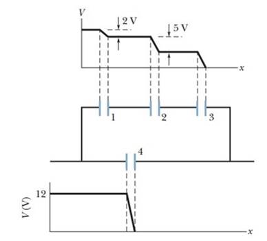
Figure 25-33 Problem 18.
Want to see the full answer?
Check out a sample textbook solution
Chapter 25 Solutions
Fundamentals Of Physics - Volume 1 Only
Additional Science Textbook Solutions
College Physics: A Strategic Approach (3rd Edition)
Physics for Scientists and Engineers
Cosmic Perspective Fundamentals
Tutorials in Introductory Physics
Life in the Universe (4th Edition)


- Suppose that the capacitance of a variable capacitor can be manually changed from 100 pF to 800 pF by turning a dial, connected to one set of plates by a shaft from 0° to 180°. With the dial set at 180° (corresponding to C — 800 pF), the capacitor is connected to a 500-V source. After charging, the capacitor is disconnected from the source, and the dial is turned to 0°. If friction is negligible, how much work is required to turn the dial from 180° to 0°?arrow_forwardA 2.0F capacitor and a 4.0F capacitor are connected in series across a 1.0-kV potential. The charged capacitors are then disconnected from the source and connected to each other with terminals of like sign together. Find the charge on each capacitor and the voltage across each capacitor.arrow_forward(i) Rank the following five capacitors from greatest to smallest capacitance, noting any cases of equality, (a) a 20-F capacitor with a 4-V potential difference between its plates (b) a 30-F capacitor with charges of magnitude 90 C on each plate (c) a capacitor with charges of magnitude 80 C on its plates, differing by 2 V in potential. (d) a 10-F capacitor storing energy 125 J (e) a capacitor storing energy 250 J with a 10-V potential difference (ii) Rank the same capacitors in part (i) from largest to smallest according to the potential difference between the plates, (iii) Rank the capacitors in part (i) in the order of the magnitudes of the charges on their plates, (iv) Rank the capacitors in part (i) in the order of the energy they store.arrow_forward
- The charge density on a disk of radius R = 12.0 cm is given by = ar, with a = 1.40 C/m3 and r measured radially outward from the origin (Fig. P26.45). What is the electric potential at point A, a distance of 40.0 cm above the disk? Hint: You will need to integrate the nonuniform charge density to find the electric potential. You will find a table of integrals helpful for performing the integration.arrow_forward(i) A battery is attached to several different capacitors connected in parallel. Which of the following statements is true? (a) All capacitors have the same charge, and the equivalent capacitance is greater than the capacitance of any of the capacitors in the group, (b) The capacitor with the largest capacitance carries the smallest charge, (c) The potential difference across each capacitor is the same, and the equivalent capacitance is greater than any of the capacitors in the group. (d) The capacitor with the smallest capacitance carries the largest charge. (e) The potential differences across the capacitors are the same only if the capacitances are the same, (ii) The capacitors are reconnected in series, and the combination is again connected to the battery. From the same choices, choose the one that is true.arrow_forwardA 10.0-F capacitor is charged to 15.0 V. It is next connected in series with an uncharged 5.00-F capacitor. The series combination is finally connected across a 50.0-V battery as diagrammed in Figure P20.83. Find the new potential differences across the 5.00-F and 10.0-F capacitors after the switch is thrown closed. Figure P20.83arrow_forward
- In Figure P27.7, capacitor 1 (C1 = 20.0 F) initially has a potential difference of 50.0 V and capacitor 2 (C2 = 5.00 F) has none. The switches are then closed simultaneously. a. Find the final charge on each capacitor after a long time has passed. b. Calculate the percentage of the initial stored energy that was lost when the switches were closed. FIGURE P27.7arrow_forwardWhat If? The two capacitors of Problem 13 (C1 = 5.00 F and C2 = 12.0 F) are now connected in series and to a 9.00-Y battery. Find (a) the equivalent capacitance of the combination. (b) the potential difference across each capacitor, and (c) the charge on each capacitor.arrow_forwardIn a certain region of space, the electric field is zero. From this fact, what can you conclude about the electric potential in this region? (a) It is zero, (b) It does not vary with position. (c) It is positive. (d) It is negative. (e) None of those answers is necessarily true.arrow_forward
- Check Your Understanding Determine the net capacitance C of each network of capacitors shown below. Assume the C1= 1.0 pF, C2=2.0pF, C3=4.0pF, and C4=5.0 pF. Find the charge on each capacitor, assuming there is a potential difference of 12.0 V across each network.arrow_forwardAccording to UE=12C(V)2 (Eq. 27.3), a greater capacitance means more energy is stored by the capacitor, but according to UE = Q2/2C (Eq. 27.2), a greater capacitance means less energy is stored. How can both of these equations be correct?arrow_forwardAn arrangement of capacitors is shown in Figure P27.23. a. If C = 9.70 105 F, what is the equivalent capacitance between points a and b? b. A battery with a potential difference of 12.00 V is connected to a capacitor with the equivalent capacitance. What is the energy stored by this capacitor? Figure P27.23 Problems 23 and 24.arrow_forward
 Physics for Scientists and Engineers: Foundations...PhysicsISBN:9781133939146Author:Katz, Debora M.Publisher:Cengage Learning
 Physics for Scientists and Engineers, Technology ...PhysicsISBN:9781305116399Author:Raymond A. Serway, John W. JewettPublisher:Cengage Learning
 Principles of Physics: A Calculus-Based TextPhysicsISBN:9781133104261Author:Raymond A. Serway, John W. JewettPublisher:Cengage Learning
 Physics for Scientists and Engineers with Modern ...PhysicsISBN:9781337553292Author:Raymond A. Serway, John W. JewettPublisher:Cengage Learning
 Physics for Scientists and EngineersPhysicsISBN:9781337553278Author:Raymond A. Serway, John W. JewettPublisher:Cengage Learning