Concept explainers
Videos
(a)
The total energy stored in the system.
(a)
Answer to Problem 56AP
Total energy stored in the system is
Explanation of Solution
Below figure shows the system of four capacitors.
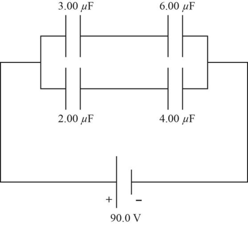
Figure-(1)
Write the expression for equivalent capacitance for series capacitors.
Here,
Write the expression for equivalent capacitance for parallel capacitors.
Here,
Write the expression for net equivalent capacitance.
Here,
Write the expression for energy stored in the system.
Here,
Conclusion:
Substitute,
Further solve the above equation.
Substitute,
Further solve the above equation.
Substitute
Substitute
Further solve the above equation.
Therefore, total energy stored in the system is
(b)
The energy stored by each capacitor.
(b)
Answer to Problem 56AP
Energy stored at
Explanation of Solution
Write the expression for charge in the capacitor.
Here,
Write the expression for energy stored in the capacitor.
Conclusion:
Substitute
Substitute
Substitute
Substitute
Substitute
Substitute
Therefore, energy stored at
(c)
The observation from part (a) and part (b).
(c)
Answer to Problem 56AP
Sum of the answers of part (a) is same as part (b).
Explanation of Solution
Write the expression for total energy stored.
Conclusion:
Substitute
Therefore, sum of the answers of part (a) is same as part (b).
Want to see more full solutions like this?
Chapter 26 Solutions
Physics: for Science.. With Modern. -Update (Looseleaf)


- An arrangement of capacitors is shown in Figure P27.23. a. If C = 9.70 105 F, what is the equivalent capacitance between points a and b? b. A battery with a potential difference of 12.00 V is connected to a capacitor with the equivalent capacitance. What is the energy stored by this capacitor? Figure P27.23 Problems 23 and 24.arrow_forwardIn Figure P27.7, capacitor 1 (C1 = 20.0 F) initially has a potential difference of 50.0 V and capacitor 2 (C2 = 5.00 F) has none. The switches are then closed simultaneously. a. Find the final charge on each capacitor after a long time has passed. b. Calculate the percentage of the initial stored energy that was lost when the switches were closed. FIGURE P27.7arrow_forwardGiven the arrangement of capacitors in Figure P27.23, find an expression for the equivalent capacitance between points a and b. Figure P27.23 Problems 23 and 24.arrow_forward
- Find the equivalent capacitance between points a and b in the combination of capacitors shown in Figure P20.51. Figure P20.51arrow_forwardFigure P27.75 shows four capacitors with CA = 4.00 F, CB = 8.00 F. CC = 6.00 F. and CD = 5.00 F connected across points a and b, which have potential difference Vab = 12.0 V. a. What is the equivalent capacitance of the four capacitors? b. What is the charge on each of the four capacitors?arrow_forwardFor the system of capacitors shown in Figure P16.41, find (a) the equivalent capacitance of the system, (b) the charge on each capacitor, and (c) the potential difference across each capacitor. Figure P16.41 Problems 41 and 60.arrow_forward
- Find (a) the equivalent capacitance of the capacitors in Figure P26.26, (b) the charge on each capacitor, and (c) the potential difference across each capacitor.arrow_forwardA parallel-plate capacitor has square plates of side s = 2.50 cm and plate separation d = 2.50 mm. The capacitor is charged by a battery to a charge Q = 4.00 C, after which the battery is disconnected. A porcelain dielectric ( = 6.5) is then inserted a distance y = 1.00 cm into the capacitor (Fig. P27.88). Hint: Consider the system as two capacitors connected in parallel. a. What is the effective capacitance of this capacitor? b. How much energy is stored in the capacitor? c. What are the magnitude and direction of the force exerted on the dielectric by the plates of the capacitor? Figure P27.88arrow_forward(a) Find the equivalent capacitance between points a and b for the group of capacitors connected as shown in Figure P20.44. Take C1 = 5.00 F, C2 = 10.0 F, and C3 = 2.00 F. (b) What charge is stored on C3 if the potential difference between points a and b is 60.0 V? Figure P20.44arrow_forward
- Consider the combination of capacitors in Figure P16.42. (a) Find the equivalent single capacitance of the two capacitors in series and redraw the diagram (called diagram 1) with this equivalent capacitance. (b) In diagram 1, find the equivalent capacitance of the three capacitors in parallel and redraw the diagram as a single battery and single capacitor in a loop. (c) Compute the charge on the single equivalent capacitor. (d) Returning to diagram 1, compute the charge on each individual capacitor. Does the sum agree with the value found in part (c)? (e) What is the charge on the 24.0-F capacitor and on the 8.00-F capacitor? Compute the voltage drop across (f) the 24.0-F capacitor and (g) the 8.00-F capacitor. Figure P16.42arrow_forward(a) Find the equivalent capacitance between points a and b for the group of capacitors connected as shown in Figure P16.46 if C1 = 5.00 F, C2 = 10.00 F, and C3 = 2.00 F. (b) If the potential between points a and b is 60.0 V, what charge is stored on C5? Figure P16.46arrow_forwardFor the system of capacitors shown in Figure P16.41, find (a) the equivalent capacitance of the system, (b) the charge on each capacitor, and (c) the potential difference across each capacitor. Figure P16.41 Problems 41 and 60.arrow_forward
 Physics for Scientists and Engineers, Technology ...PhysicsISBN:9781305116399Author:Raymond A. Serway, John W. JewettPublisher:Cengage Learning
 College PhysicsPhysicsISBN:9781305952300Author:Raymond A. Serway, Chris VuillePublisher:Cengage Learning
 College PhysicsPhysicsISBN:9781285737027Author:Raymond A. Serway, Chris VuillePublisher:Cengage Learning
 Physics for Scientists and Engineers: Foundations...PhysicsISBN:9781133939146Author:Katz, Debora M.Publisher:Cengage Learning
 Principles of Physics: A Calculus-Based TextPhysicsISBN:9781133104261Author:Raymond A. Serway, John W. JewettPublisher:Cengage Learning
 Physics for Scientists and Engineers with Modern ...PhysicsISBN:9781337553292Author:Raymond A. Serway, John W. JewettPublisher:Cengage Learning