
Videos
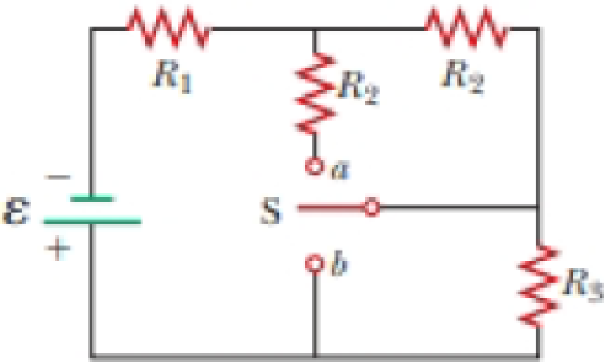
A battery with emf ε and no internal resistance supplies current to the circuit shown in Figure P27.9. When the double-throw switch S is open as shown in the figure, the current in the battery is I0. When the switch is closed in position a, the current in the battery is Ia. When the switch is closed in position b, the current in the battery is Ib. Find the resistances (a) R1, (b) R2, and (c) R3.
Figure P27.9 Problems 9 and 10.
(a)
The expression of the resistance
Answer to Problem 10P
The expression of the resistance
Explanation of Solution
Given information: Emf across the battery is
When the switch S is open, then the three resistors
Formula to calculate the equivalent resistance across the circuit, when the switch S is open.
Here,
As the total emf across the battery is equal to the voltage across the battery.
Here,
Substitute
Formula to calculate the equivalent resistance across the circuit, when the switch S is open.
Here,
Substitute
When the switch is closed in position
From equation (2), formula to calculate the equivalent resistance across the circuit, when the switch is closed in position
Here,
Formula to calculate the resistance when the resistors are connected in parallel.
From equation (3), formula to calculate the equivalent resistance across the circuit, when the switch is closed in position
Substitute
Substitute
When the switch is closed in position
From equation (2), formula to calculate the equivalent resistance across the circuit, when the switch is closed in position
Here,
From equation (3), formula to calculate the equivalent resistance across the circuit, when the switch is closed in position
Substitute
Subtract equation (11) from (4) to find
Thus, the expression of the resistance
Subtract equation (11) from (8) to find
Substitute
Thus, the expression of the resistance
Substitute
Thus, the expression of the resistance
Conclusion:
Therefore, the expression of the resistance
(b)
The expression of the resistance
Answer to Problem 10P
The expression of the resistance
Explanation of Solution
Given information: Emf across the battery is
From part (a) equation (17), the expression for the resistance
Thus, the expression of the resistance
Conclusion:
Therefore, the expression of the resistance
(c)
The expression of the resistance
Answer to Problem 10P
The expression of the resistance
Explanation of Solution
Given information: Emf across the battery is
From part (a) equation (15), the expression for the resistance
Thus, the expression of the resistance
Conclusion:
Therefore, the expression of the resistance
Want to see more full solutions like this?
Chapter 27 Solutions
Physics for Scientists and Engineers with Modern Physics
Additional Science Textbook Solutions
Introduction to Electrodynamics
Life in the Universe (4th Edition)
Physics: Principles with Applications
Applied Physics (11th Edition)
Conceptual Physical Science (6th Edition)


- In the circuit of Figure P27.25, the switch S has been open for a long time. It is then suddenly closed. Take = 10.0 V, R1 = 50.0 k, R2 = 100 k, and C = 10.0 F. Determine the time constant (a) before the switch is closed and (b) after the switch is closed. (c) Let the switch be closed at t = 0. Determine the current in the switch as a function of time. Figure P27.25 Problems 25 and 26.arrow_forwardA battery with = 6.00 V and no internal resistance supplies current to the circuit shown in Figure P27.9. When the double-throw switch S is open as shown in the figure, the current in the battery is 1.00 mA. When the switch is closed in position a, the current in the battery is 1.20 mA. When the switch is closed in position b, the current in the battery is 2.00 mA. Find the resistances (a) R1, (b) R2, and (c) R3. Figure P27.9 Problems 9 and 10.arrow_forwardIn Figure P29.81, N real batteries, each with an emf and internal resistance r, are connected in a closed ring. A resistor R can be connected across any two points of this ring, causing there to be n real batteries in one branch and N n resistors in the other branch. Find an expression for the current through the resistor R in this case.arrow_forward
- Consider a series RC circuit as in Figure P28.38 for which R = 1.00 M, C = 5.00 F, and = 30.0 V. Find (a) the time constant of the circuit and (b) the maximum charge on the capacitor after the switch is thrown closed. (c) Find the current in the resistor 10.0 s after the switch is closed.arrow_forwardA circuit consists of three identical lamps connected to a battery as in Figure OQ28.14. The battery has some internal resistance. The switch S, originally open, is closed. (i) What then happens to the brightness of lamp B? (a) It increases. (b) It decreases somewhat. (c) It does not change. (d) It drops to zero. For parts (ii) to (vi), choose from the same possibilities (a) through (d). (ii) What happens to the brightness of lamp C? (iii) What happens to the current in the battery? (iv) What happens to the potential difference across lamp A? (v) What happens to the potential difference across lamp C? (vi) What happens to the total power delivered to the lamps by the battery?arrow_forwardFigure P29.77 shows a circuit with two batteries and three resistors. a. How much current flows through the 2.00- resistor? b. What is the potential difference between points a and b in the circuit?arrow_forward
- Figure P29.60 shows a simple RC circuit with a 2.50-F capacitor, a 3.50-M resistor, a 9.00-V emf, and a switch. What are a. the charge on the capacitor, b. the current in the resistor, c. the rate at which the capacitor is storing energy, and d. the rate at which the battery is delivering energy exactly 7.50 s alter the switch is closed?arrow_forwardIn the circuit of Figure P27.25, the switch S has been open for a long time. It is then suddenly closed. Determine the time constant (a) before the switch is closed and (b) after the switch is closed. (c) Let the switch be closed at t = 0. Determine the current in the switch as a function of time. Figure P27.25 Problems 25 and 26.arrow_forwardFigure P29.46 shows a circuit with a 12.0-V battery connected to four resistors. How much power is delivered to each resistor?arrow_forward
- What is the equivalent resistance between points a and b of the six resistors shown in Figure P29.70? FIGURE P29.70arrow_forwardThe emfs in Figure P29.43 are 1 = 6.00 V and 2 = 12.0 V. The resistances are R1 = 15.0 , R2 = 30.0 , R3 = 45.0 , and R4 = 60.0 . Find the current in each resistor when the switch is a. open and b. closed.arrow_forwardFigure P29.84 shows a circuit that consists of two identical emf devices. If R1 = R2 = R and the switch is closed, find an expression (in terms of R and ) for the current I that is in the branch from point a to b.arrow_forward
 Physics for Scientists and Engineers with Modern ...PhysicsISBN:9781337553292Author:Raymond A. Serway, John W. JewettPublisher:Cengage Learning
 Physics for Scientists and EngineersPhysicsISBN:9781337553278Author:Raymond A. Serway, John W. JewettPublisher:Cengage Learning
 Physics for Scientists and Engineers: Foundations...PhysicsISBN:9781133939146Author:Katz, Debora M.Publisher:Cengage Learning
 Principles of Physics: A Calculus-Based TextPhysicsISBN:9781133104261Author:Raymond A. Serway, John W. JewettPublisher:Cengage Learning
 Physics for Scientists and Engineers, Technology ...PhysicsISBN:9781305116399Author:Raymond A. Serway, John W. JewettPublisher:Cengage Learning
 College PhysicsPhysicsISBN:9781305952300Author:Raymond A. Serway, Chris VuillePublisher:Cengage Learning