
Physics for Scientists and Engineers with Modern Physics
10th Edition
ISBN: 9781337553292
Author: Raymond A. Serway, John W. Jewett
Publisher: Cengage Learning
expand_more
expand_more
format_list_bulleted
Videos
Textbook Question
Chapter 27, Problem 46AP
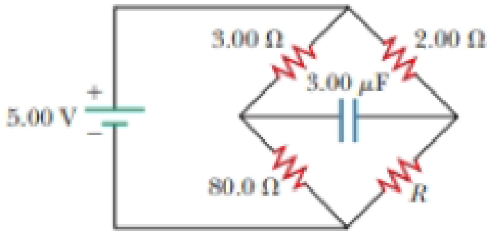
(a) Determine the equilibrium charge on the capacitor in the circuit of Figure P27.46 as a function of R. (b) Evaluate the charge when R = 10.0 Ω. (c) Can the charge on the capacitor be zero? If so, for what value of R? (d) What is the maximum possible magnitude of the charge on the capacitor? For what value of R is it achieved? (c) Is it experimentally meaningful to take R = ∞? Explain your answer. If so, what charge magnitude does it imply?
Figure P27.46
Expert Solution & Answer

Trending nowThis is a popular solution!

Students have asked these similar questions
The circuit in Figure P28.43 has been connected for a long time. (a) What is the potential difference acros:s the capacitor? (b) If the battery is disconnected from the circuit, over what time interval does the capacitor discharge to one-tenth its initial voltage? 1.00 Ω 8.00 Ω 1.00 μF 0.0 V 4.00 Ω 2.00 Ω
The figure shows how a bleeder resistor is used to discharge a capacitor after an electronic device is shut off, allowing a person to work on the electronics with less risk of shock. The resistor has a resistance of 284 kΩΩ.
(a)
What is the time constant?
s ( ± 0.1 s)
(b)
How long will it take to reduce the voltage on the capacitor to 1.0% of its full value once discharge begins?
s ( ± 1 s)
(c)
If the capacitor is charged to a voltage ?0V0 through a 109 ΩΩ resistance, calculate the time it takes to rise to 0.9?0V0 (This is close to two time constants, but you should calculate it precisely.)
ms ( ± 0.1 ms)
In an RC circuit, if we change the resistance to one with a higher value, we would expect that:
A. The area under the curve changes
B. Capacitor discharges faster
C. The capacitor takes longer to achieve Q max
D. Change the Vc voltage when the capacitor charges
Chapter 27 Solutions
Physics for Scientists and Engineers with Modern Physics
Ch. 27.1 - To maximize the percentage of the power from the...Ch. 27.2 - With the switch in the circuit of Figure 27.4a...Ch. 27.2 - With the switch in the circuit of Figure 27.6a...Ch. 27.2 - Prob. 27.4QQCh. 27.4 - Consider the circuit in Figure 27.17 and assume...Ch. 27 - Two 1.50-V batterieswith their positive terminals...Ch. 27 - As in Example 27.2, consider a power supply with...Ch. 27 - Figure P27.3 shows the interior of a three-way...Ch. 27 - Prob. 4PCh. 27 - Consider the two circuits shown in Figure P27.5 in...
Ch. 27 - Consider strings of incandescent lights that are...Ch. 27 - You are working at an electronics fabrication...Ch. 27 - In your new job at an engineering company, your...Ch. 27 - A battery with = 6.00 V and no internal...Ch. 27 - A battery with emf and no internal resistance...Ch. 27 - Todays class on current and resistance is about to...Ch. 27 - Why is the following situation impossible? A...Ch. 27 - Calculate the power delivered to each resistor in...Ch. 27 - For the purpose of measuring the electric...Ch. 27 - Four resistors are connected to a battery as shown...Ch. 27 - You have a faculty position at a community college...Ch. 27 - The circuit shown in Figure P27.17 is connected...Ch. 27 - The following equations describe an electric...Ch. 27 - Taking R = 1.00 k and = 250 V in Figure P27.19,...Ch. 27 - In the circuit of Figure P27.20, the current I1 =...Ch. 27 - (a) Can the circuit shown in Figure P27.21 be...Ch. 27 - For the circuit shown in Figure P27.22, we wish to...Ch. 27 - An uncharged capacitor and a resistor are...Ch. 27 - Prob. 24PCh. 27 - In the circuit of Figure P27.25, the switch S has...Ch. 27 - In the circuit of Figure P27.25, the switch S has...Ch. 27 - A 10.0-F capacitor is charged by a 10.0-V battery...Ch. 27 - Prob. 28PCh. 27 - Prob. 29PCh. 27 - Prob. 30PCh. 27 - Prob. 31PCh. 27 - Prob. 32APCh. 27 - Find the equivalent resistance between points a...Ch. 27 - The circuit in Figure P27.34a consists of three...Ch. 27 - The circuit in Figure P27.35 has been connected...Ch. 27 - The resistance between terminals a and b in Figure...Ch. 27 - (a) Calculate the potential difference between...Ch. 27 - Why is the following situation impossible? A...Ch. 27 - When two unknown resistors are connected in series...Ch. 27 - Prob. 40APCh. 27 - The circuit in Figure P27.41 contains two...Ch. 27 - Prob. 42APCh. 27 - A power supply has an open-circuit voltage of 40.0...Ch. 27 - A battery is used to charge a capacitor through a...Ch. 27 - Prob. 45APCh. 27 - (a) Determine the equilibrium charge on the...Ch. 27 - In Figure P27.47, suppose the switch has been...Ch. 27 - Figure P27.48 shows a circuit model for the...Ch. 27 - The student engineer of a campus radio station...Ch. 27 - Prob. 50APCh. 27 - The switch in Figure P27.51a closes when Vc23Vand...
Additional Science Textbook Solutions
Find more solutions based on key concepts
Order of Magnitude Estimate. Mathematical Insight 1.3 defines order of magnitude estimates, and in the text we ...
The Cosmic Perspective (9th Edition)
5.106 A 70-kg person rides in a 30-kg cart moving at 12 m/s at the top of a hill that is in the shape of an arc...
University Physics (14th Edition)
What is the maximum magnetic intensity in a plane electromagnetic wave whose maximum electric intensity is 100 ...
Introduction To Health Physics
You have a summer job at your universitys zoology department, where youll be working with an animal behavior ex...
Essential University Physics: Volume 1 (3rd Edition)
Knowledge Booster


Learn more about
Need a deep-dive on the concept behind this application? Look no further. Learn more about this topic, physics and related others by exploring similar questions and additional content below.Similar questions
- The circuit in Figure P21.59 has been connected for a long time. (a) What is the potential difference across the capacitor? (b) If the battery is disconnected from the circuit, over what time interval does the capacitor discharge to one-tenth its initial voltage?arrow_forward(a) Determine the equilibrium charge on the capacitor in the circuit of Figure P27.46 as a function of R. (b) Evaluate the charge when R = 10.0 . (c) Can the charge on the capacitor be zero? If so, for what value of R? (d) What is the maximum possible magnitude of the charge on the capacitor? For what value of R is it achieved? (c) Is it experimentally meaningful to take R = ? Explain your answer. If so, what charge magnitude does it imply? Figure P27.46arrow_forwardA capacitor with initial charge Q0 is connected across a resistor R at time t = 0. The separation between the plates of the capacitor changes as d = d0/(1 + t) for 0 t 1 s. Find an expression for the voltage drop across the capacitor as a function of time.arrow_forward
- The circuit shown in Figure P28.78 is set up in the laboratory to measure an unknown capacitance C in series with a resistance R = 10.0 M powered by a battery whose emf is 6.19 V. The data given in the table are the measured voltages across the capacitor as a function of lime, where t = 0 represents the instant at which the switch is thrown to position b. (a) Construct a graph of In (/v) versus I and perform a linear least-squares fit to the data, (b) From the slope of your graph, obtain a value for the time constant of the circuit and a value for the capacitance. v(V) t(s) In (/v) 6.19 0 5.56 4.87 4.93 11.1 4.34 19.4 3.72 30.8 3.09 46.6 2.47 67.3 1.83 102.2arrow_forwardA charge Q is placed on a capacitor of capacitance C. The capacitor is connected into the circuit shown in Figure P26.37, with an open switch, a resistor, and an initially uncharged capacitor of capacitance 3C. The switch is then closed, and the circuit comes to equilibrium. In terms of Q and C, find (a) the final potential difference between the plates of each capacitor, (b) the charge on each capacitor, and (c) the final energy stored in each capacitor. (d) Find the internal energy appearing in the resistor. Figure P26.37arrow_forwardAssume a length of axon membrane of about 0.10 m is excited by an action potential (length excited = nerve speed pulse duration = 50.0 m/s 2.0 103 s = 0.10 m). In the resting state, the outer surface of the axon wall is charged positively with K+ ions and the inner wall has an equal and opposite charge of negative organic ions, as shown in Figure P18.43. Model the axon as a parallel-plate capacitor and take C = 0A/d and Q = C V to investigate the charge as follows. Use typical values for a cylindrical axon of cell wall thickness d = 1.0 108 m, axon radius r = 1.0 101 m, and cell-wall dielectric constant = 3.0. (a) Calculate the positive charge on the outside of a 0.10-m piece of axon when it is not conducting an electric pulse. How many K+ ions are on the outside of the axon assuming an initial potential difference of 7.0 102 V? Is this a large charge per unit area? Hint: Calculate the charge per unit area in terms of electronic charge e per squared (2). An atom has a cross section of about 1 2 (1 = 1010 m). (b) How much positive charge must flow through the cell membrane to reach the excited state of + 3.0 102 V from the resting state of 7.0 102 V? How many sodium ions (Na+) is this? (c) If it takes 2.0 ms for the Na+ ions to enter the axon, what is the average current in the axon wall in this process? (d) How much energy does it take to raise the potential of the inner axon wall to + 3.0 102 V, starting from the resting potential of 7.0 102 V? Figure P18.43 Problem 43 and 44.arrow_forward
- Figure P18.26 shows a voltage divider, a circuit used to obtain a desired voltage Vout from a source voltage . Determine the required value of R2 if = 5.00 V, Vout = 1.50 V and R1 = 1.00 103 (Hint: Use Kirchhoff's loop rule, substituting Vout = IR2, to find the current. Then solve Ohms law for R2. Figure P18.26arrow_forwardFigure P18.26 shows a voltage divider, a circuit used to obtain a desired voltage Vout from a source voltage . Determine the required value of R2 if = 5.00 V, Vout = 1.50 V and R1 = 1.00 103 (Hint: Use Kirchhoff's loop rule, substituting Vout = IR2, to find the current. Then solve Ohms law for R2. Figure P18.26arrow_forwardAn ECG monitor must have an KC time constant lessthan 1.00102s to be able to measure variations involtage oversmall time intervals, (a) If the resistance of the circuit (duemostly to that of the patient's chest) is 1.00kTwhat is the maximum capacitance of the circuit?(b) Would It be difficult in practice to limit the capacitance to less than the value found in (a)?arrow_forward
- A Pairs of parallel wires or coaxial cables are two conductors separated by an insulator, so they have a capacitance. For a given cable, the capacitance is independent of the length if the cable is very long. A typical circuit model of a cable is shown in Figure P27.87. It is called a lumped-parameter model and represents how a unit length of the cable behaves. Find the equivalent capacitance of a. one unit length (Fig. P27.87A), b. two unit lengths (Fig. P27.87B), and c. an infinite number of unit lengths (Fig. P27.87C). Hint: For the infinite number of units, adding one more unit at the beginning does not change the equivalent capacitance.arrow_forwardWhen charging a capacitor in series with a resistor, using a 10 V emf source, what would you expect the voltage of the capacitor to be at an initial time of t = τ ? a. 3.68 V b. 0.368 V c. 6.32 V d. 10 V e. 0.632 Varrow_forwardA capacitor of capacitance C = 4.5 uF is initially uncharged. It is connected in series with a switch of negligible resistance, a resistor of resistance R = 8.5 kOhm, and a battery which provides a potential difference of VB = 105V. (a) Calculate the time constant t for the circuit in seconds. (b) After a very long time after the switch has been closed, what is the voltage drop VC across the capacitor in terms of VB? (c) Calculate the charge Q on the capacitor a very long time after the switch has been closed in C. (d) Calculate the current I a very long time after the switch has been closed in A. (e) Calculate the time t after which the current through the resistor in one-third of its maximum value in s. (f) Calculate the cahrge Q on the capacitor when the current in the resistor equals one third its maximum value in C.arrow_forward
arrow_back_ios
SEE MORE QUESTIONS
arrow_forward_ios
Recommended textbooks for you
 Physics for Scientists and EngineersPhysicsISBN:9781337553278Author:Raymond A. Serway, John W. JewettPublisher:Cengage Learning
 Physics for Scientists and Engineers with Modern ...PhysicsISBN:9781337553292Author:Raymond A. Serway, John W. JewettPublisher:Cengage Learning
 Physics for Scientists and Engineers: Foundations...PhysicsISBN:9781133939146Author:Katz, Debora M.Publisher:Cengage Learning
 Principles of Physics: A Calculus-Based TextPhysicsISBN:9781133104261Author:Raymond A. Serway, John W. JewettPublisher:Cengage Learning
 College PhysicsPhysicsISBN:9781305952300Author:Raymond A. Serway, Chris VuillePublisher:Cengage Learning
 College PhysicsPhysicsISBN:9781285737027Author:Raymond A. Serway, Chris VuillePublisher:Cengage Learning
Physics for Scientists and Engineers
Physics
ISBN:9781337553278
Author:Raymond A. Serway, John W. Jewett
Publisher:Cengage Learning
Physics for Scientists and Engineers with Modern ...
Physics
ISBN:9781337553292
Author:Raymond A. Serway, John W. Jewett
Publisher:Cengage Learning
Physics for Scientists and Engineers: Foundations...
Physics
ISBN:9781133939146
Author:Katz, Debora M.
Publisher:Cengage Learning
Principles of Physics: A Calculus-Based Text
Physics
ISBN:9781133104261
Author:Raymond A. Serway, John W. Jewett
Publisher:Cengage Learning
College Physics
Physics
ISBN:9781305952300
Author:Raymond A. Serway, Chris Vuille
Publisher:Cengage Learning
College Physics
Physics
ISBN:9781285737027
Author:Raymond A. Serway, Chris Vuille
Publisher:Cengage Learning
DC Series circuits explained - The basics working principle; Author: The Engineering Mindset;https://www.youtube.com/watch?v=VV6tZ3Aqfuc;License: Standard YouTube License, CC-BY