Concept explainers
Videos
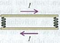
DATA A pair of long, rigid metal rods, each of length 0.50 m, lie parallel to each other on a frictionless table. Their ends are connected by identical, very lightweight
Figure P28.78
Want to see the full answer?
Check out a sample textbook solution
Chapter 28 Solutions
University Physics, Volume 2 (Chs. 21-37) (14th Edition)
Additional Science Textbook Solutions
Essential University Physics: Volume 2 (3rd Edition)
College Physics: A Strategic Approach (3rd Edition)
Conceptual Physical Science (6th Edition)
University Physics Volume 1
Lecture- Tutorials for Introductory Astronomy
Physics: Principles with Applications


- Three long, current-carrying wires are parallel to one another and separated by a distance d. The magnitudes and directions of the currents are shown in Figure P30.91. Wires 1 and 3 are fixed, but wire 2 is free to move. Wire 2 is displaced to the right by a small distance x. Determine the net force (per unit length) acting on wire 2 and the angular frequency of the resulting oscillation. Assume the mass per unit length of wire 2 is and x d. FIGURE P30.91arrow_forwardIn Figure P30.38, the rolling axle, 1.50 m long, is pushed along horizontal rails at a constant speed v = 3.00 m/s. A resistor R = 0.400 is connected to the rails at points a and b, directly opposite each other. The wheels make good electrical contact with the rails, so the axle, rails, and R form a closed-loop circuit. The only significant resistance in the circuit is R. A uniform magnetic field B = 0.080 0 T is vertically downward. (a) Find the induced current I in the resistor. (b) What horizontal force F is required to keep the axle rolling at constant speed? (c) Which end of the resistor, a or b, is at the higher electric potential? (d) What If? After the axle rolls past the resistor, does the current in R reverse direction? Explain your answer. Figure P30.38arrow_forwardConsider the apparatus shown in Figure P30.32: a conducting bar is moved along two rails connected to an incandescent lightbulb. The whole system is immersed in a magnetic field of magnitude B = 0.400 T perpendicular and into the page. The distance between the horizontal rails is = 0.800 m. The resistance of the lightbulb is R = 48.0 , assumed to be constant. The bar and rails have negligible resistance. The bar is moved toward the right by a constant force of magnitude F = 0.600 N. We wish to find the maximum power delivered to the lightbulb. (a) Find an expression for the current in the lightbulb as a function of B, , R, and v, the speed of the bar. (b) When the maximum power is delivered to the lightbulb, what analysis model properly describes the moving bar? (c) Use the analysis model in part (b) to find a numerical value for the speed v of the bar when the maximum power is being delivered to the lightbulb. (d) Find the current in the lightbulb when maximum power is being delivered to it. (e) Using P = I2R, what is the maximum power delivered to the lightbulb? (f) What is the maximum mechanical input power delivered to the bar by the force F? (g) We have assumed the resistance of the lightbulb is constant. In reality, as the power delivered to the lightbulb increases, the filament temperature increases and the resistance increases. Does the speed found in part (c) change if the resistance increases and all other quantities are held constant? (h) If so, does the speed found in part (c) increase or decrease? If not, explain. (i) With the assumption that the resistance of the lightbulb increases as the current increases, does the power found in part (f) change? (j) If so, is the power found in part (f) larger or smaller? If not, explain. Figure P30.32arrow_forward
- Consider the system pictured in Figure P28.26. A 15.0-cm horizontal wire of mass 15.0 g is placed between two thin, vertical conductors, and a uniform magnetic field acts perpendicular to the page. The wire is free to move vertically without friction on the two vertical conductors. When a 5.00-A current is directed as shown in the figure, the horizontal wire moves upward at constant velocity in the presence of gravity. (a) What forces act on the horizontal wire, and (b) under what condition is the wire able to move upward at constant velocity? (c) Find the magnitude and direction of the minimum magnetic Field required to move the wire at constant speed. (d) What happens if the magnetic field exceeds this minimum value? Figure P28.26arrow_forwardIn Figure P20.65 the rolling axle of length 1.50 m is pushed along horizontal rails at a constant speed v = 3.00 m/s. A resist or R = 0.400 is connected to the rails at points a and b, directly opposite each other. (The wheels make good electrical contact with the rails, so the axle, rails, and R form a closed-loop circuit. The only significant resistance in the circuit is R.) A uniform magnetic field B = 0.800 T is directed vertically downward. (a) Find the induced current I in the resistor. (b) What horizontal force F is required to keep the axle rolling at constant speed? (c) Which end of the resistor, a or b. is at the higher electric potential? (d) Alter the axle rolls past the resistor, does the current in R reverse direction? Explain your answer. Figure P20.65arrow_forwardReview. Rail guns have been suggested for launching projectiles into space without chemical rockets. A tabletop model rail gun (Fig. P22.76) consists of two long, parallel, horizontal rails = 3.50 cm apart, bridged by a bar of mass m = 3.00 g that is free to slide without friction. The rails and bar have low electric resistance, and the current is limited to a constant I = 24.0 A by a power supply that is far to the left of the figure, so it has no magnetic effect on the bar. Figure P22.76 shows the bar at rest at the midpoint of the rails at the moment the current is established. We wish to find the speed with which the bar leaves the rails after being released from the midpoint of the rails. (a) Find the magnitude of the magnetic field at a distance of 1.75 cm from a single long wire carrying a current of 2.40 A. (b) For purposes of evaluating the magnetic field, model the rails as infinitely long. Using the result of part (a), find the magnitude and direction of the magnetic field at the midpoint of the bar. (c) Argue that this value of the field will be the same at all positions of the bar to the right of the midpoint of the rails. At other points along the bar, the field is in the same direction as at the midpoint, but is larger in magnitude. Assume the average effective magnetic field along the bar is five times larger than the field at the midpoint. With this assumption, find (d) the magnitude and (e) the direction of the force on the bar. (f) Is the bar properly modeled as a particle under constant acceleration? (g) Find the velocity of the bar after it has traveled a distance d = 130 cm to the end of the rails. Figure P22.76arrow_forward
- A rectangular conducting loop is placed near a long wire carrying a current I as shown in Figure OQ23.5. If I decreases in time, what can be said of the current induced in the loop? (a) The direction of the current depends on the size of the loop. (b) The current is clockwise. (c) The current is counterclockwise. (d) The current is zero. (e) Nothing can be said about the current in the loop without more information.arrow_forwardA conducting rod of length = 35.0 cm is free to slide on two parallel conducting bars as shown in Figure P30.35. Two resistors R1 = 2.00 and R2 = 5.00 are connected across the ends of the bars to form a loop. A constant magnetic field B = 2.50 T is directed perpendicularly into the page. An external agent pulls the rod to the left with a constant speed of v = 8.00 m/s. Find (a) the currents in both resistors, (b) the total power delivered to the resistance of the circuit, and (c) the magnitude of the applied force that is needed to move the rod with this constant velocity. Figure P30.35arrow_forwardReview. In Figure P30.42, a uniform magnetic field decreases at a constant rate dB/dt = K, where K is a positive constant. A circular loop of wire of radius a containing a resistance R and a capacitance C is placed with its plane normal to the field. (a) Find the charge Q on the capacitor when it is fully charged. (b) Which plate, upper or lower, is at the higher potential? (c) Discuss the force that causes the separation of charges. Figure P30.42arrow_forward
 Physics for Scientists and Engineers: Foundations...PhysicsISBN:9781133939146Author:Katz, Debora M.Publisher:Cengage Learning
 Physics for Scientists and Engineers with Modern ...PhysicsISBN:9781337553292Author:Raymond A. Serway, John W. JewettPublisher:Cengage Learning
 Physics for Scientists and EngineersPhysicsISBN:9781337553278Author:Raymond A. Serway, John W. JewettPublisher:Cengage Learning
 Principles of Physics: A Calculus-Based TextPhysicsISBN:9781133104261Author:Raymond A. Serway, John W. JewettPublisher:Cengage Learning
 College PhysicsPhysicsISBN:9781305952300Author:Raymond A. Serway, Chris VuillePublisher:Cengage Learning