
Videos
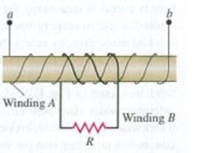
A cardboard tube is wrapped with two windings of insulated wire wound in opposite directions, as shown in Fig. E29.20. Terminals a and b of winding A may be connected to a battery through a reversing switch. State whether the induced current in the resistor R is from left to right or from right to left in the following circumstances: (a) the current in winding A is from a to b and is increasing; (b) the current in winding A is from b to a and is decreasing; (c) the current in winding A is from b to a and is increasing.
Figure E29.20

Learn your wayIncludes step-by-step video

Chapter 29 Solutions
University Physics with Modern Physics (14th Edition)
Additional Science Textbook Solutions
Introduction to Electrodynamics
University Physics (14th Edition)
The Cosmic Perspective (8th Edition)
Essential University Physics: Volume 1 (3rd Edition)
Life in the Universe (4th Edition)
Conceptual Physical Science (6th Edition)


- Figure P23.58 is a graph of the induced emf versus time for a coil of N turns rotating with angular speed ω in a uniform magnetic field directed perpendicular to the coil’s axis of rotation. What If? Copy this sketch (on a larger scale) and on the same set of axes show the graph of emf versus t (a) if the number of turns in the coil is doubled, (b) if instead the angular speed is doubled, and (c) if the angular speed is doubled while the number of turns in the coil is halved. Figure P23.58arrow_forwardA rectangular conducting loop is placed near a long wire carrying a current I as shown in Figure OQ23.5. If I decreases in time, what can be said of the current induced in the loop? (a) The direction of the current depends on the size of the loop. (b) The current is clockwise. (c) The current is counterclockwise. (d) The current is zero. (e) Nothing can be said about the current in the loop without more information.arrow_forwardA square, flat loop of wire is pulled at constant velocity through a region of uniform magnetic field directed perpendicular to the plane of the loop as shown in Figure OQ23.9. Which of the following statements are correct? More than one statement may be correct. (a) Current is induced in the loop in the clockwise direction. (b) Current is induced in the loop in the counterclockwise direction. (c) No current is induced in the loop. (d) Charge separation occurs in the loop, with the top edge positive. (e) Charge separation occurs in the loop, with the top edge negative.arrow_forward
- A piece of insulated wire is shaped into a figure eight as shown in Figure P23.12. For simplicity, model the two halves of the figure eight as circles. The radius of the upper circle is 5.00 cm and that of the lower circle is 9.00 cm. The wire has a uniform resistance per unit length of 3.00 Ω/m. A uniform magnetic field is applied perpendicular to the plane of the two circles, in the direction shown. The magnetic field is increasing at a constant rate of 2.00 T/s. Find (a) the magnitude and (b) the direction of the induced current in the wire. Figure P23.12arrow_forwardA Figure P32.74 shows an N-turn rectangular coil of length a and width b entering a region of uniform magnetic field of magnitude Bout directed out of the page. The velocity of the coil is constant and is upward in the figure. The total resistance of the coil is R. What are the magnitude and direction of the magnetic force on the coil a. when only a portion of the coil has entered the region with the field, b. when the coil is completely embedded in the field, and c. as the coil begins to exit the region with the field?arrow_forwardA rectangular coil consists of N = 100 closely wrapped turns and has dimensions a = 0.400 m and b = 0.300 m. The coil is hinged along the y axis, and its plane makes an angle = 30.0 with the x axis (Fig. P22.25). (a) What is the magnitude of the torque exerted on the coil by a uniform magnetic field B = 0.800 T directed in the positive x direction when the current is I = 1.20 A in the direction shown? (b) What is the expected direction of rotation of the coil? Figure P22.25arrow_forward
- An airplane wingspan can be approximated as a conducting rod of length 30 m. As the airplane flies due north, it is flying at a rate of 78 m/s through the Earth's magnetic field, which has a magnitude of 46 µT toward the north in a direction 57° below the horizontal plane. What is the Hall emf (in V) along the wingspan?arrow_forwardConsider the system pictured in Figure P19.21. A 15-cm length of conductor of mass 15 g, free to move vertically, is placed between two thin, vertical conductors, and a uniform magnetic field acts perpendicular to the page. When a 5.0-A current is directed as shown in the figure, the horizontal wire moves upward at constant velocity in the presence of gravity. (a) What forces act on the horizontal wire, and under what condition is the wire able to move upward at constant velocity? (b) Find the magnitude and direction of the minimum magnetic field required to move the wire at constant speed. (c) What happens if the magnetic field exceeds this minimum value? (The wire slides without friction on the two vertical conductors.) snipparrow_forwardA square wire loop (side length 1.5 m) is oriented so that it is perpendicular to an external magnetic field B, with half the area of the loop embedded in the field, as shown below. The loop contains a battery with a constant emf Eb = 7.2 V and a resistor R = 3.2 Ω. The external magnetic field is B(t) = [0.027 T − (0.56 T/s) t] î where î is out of the page. (a) Findtheemfproducedbyinductionintheloop. (b) Findthenetcurrentintheloopfromboththeinducedemfandthebattery. (c) What direction is the current in? (a) Findtheemfproducedbyinductionintheloop. (b) Findthenetcurrentintheloopfromboththeinducedemfandthebattery. (c) What direction is the current in? (a) Find the emf produced by induction in the loop. (b) Find the net current in the loop from both the induced emf and the battery. (c) What direction is the current in?arrow_forward
- A long solenoid of radius r = 2.00 cm is wound with 3.50 × 10³ turns/m and carries a current that changes at the rate of 28.5 A/s as in Figure P20.60. What is the magnitude of the emf induced in the square conducting loop surrounding the center of the solenoid?arrow_forwardA nonconducting sphere has mass 80.0 g and radius 20.0 cm. A flat, compact coil ofwire with five turns is wrapped tightly around it, with each turn concentric with thesphere. The sphere is placed on an inclined plane that slopes downward to the left(Fig. P29.69), making an angle 0 with the horizontal so that the coil is parallel to theinclined plane. A uniform magnetic field of 0.350 T vertically upward exists in theregion of the sphere. (a) What current in the coil will enable the sphere to rest inequilibrium on the inclined plane? (b) Show that the result does not depend on thevalue of θ.arrow_forwardA conducting rod spans a gap of length L = 0.085 m and acts as the fourth side of a rectangular conducting loop, as shown in the figure. A constant magnetic field with magnitude B = 0.45 T pointing into the paper is in the region. The rod is pulled to the right by an external force, and moves with constant speed v = 0.11 m/s. The resistance in the wire is R = 110 Ω.Randomized Variables L = 0.085 mB = 0.45 Tv = 0.11 m/sR = 110 Ω a. Express the magnitude of the magnetic flux going through the loop, Φ, in terms of B, a and L. b. Express the change in the magnetic flux, ΔΦ, in terms of B, L, v and Δt. c. Express the magnitude of the average emf induced in the loop, ε, in terms of B, L, v. d. Express the current induced in the loop, I, in terms of ε and R.arrow_forward
 Principles of Physics: A Calculus-Based TextPhysicsISBN:9781133104261Author:Raymond A. Serway, John W. JewettPublisher:Cengage Learning
 College PhysicsPhysicsISBN:9781285737027Author:Raymond A. Serway, Chris VuillePublisher:Cengage Learning
 Physics for Scientists and Engineers: Foundations...PhysicsISBN:9781133939146Author:Katz, Debora M.Publisher:Cengage Learning