
Concept explainers
Videos
DATA You measure the magnitude of the external force
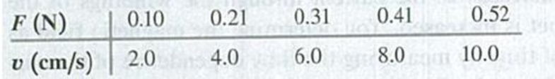
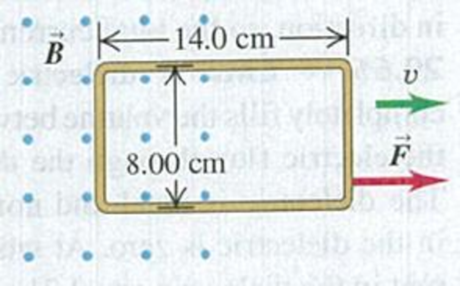
(a) Plot the data as a graph of F versus ʋ. Explain why the data points plotted this way lie close to a straight line, and determine the slope of the best-fit straight line for the data. (b) Use your graph from part (a) to calculate the magnitude B of the uniform magnetic field. (c) In Fig. P29.68, is the current induced in the loop clockwise or counterclockwise? (d) At what rate is electrical energy being dissipated in the loop when the speed of the loop is 5.00 cm/s?
Figure P29.68

Trending nowThis is a popular solution!

Chapter 29 Solutions
University Physics with Modern Physics (14th Edition)
Additional Science Textbook Solutions
University Physics Volume 2
Essential University Physics (3rd Edition)
Physics for Scientists and Engineers: A Strategic Approach with Modern Physics (4th Edition)
The Cosmic Perspective (8th Edition)
Lecture- Tutorials for Introductory Astronomy
Physics (5th Edition)


- A circular coil 15.0 cm in radius and composed of 145 tightly wound turns carries a current of 2.50 A in the counterclockwise direction, where the plane of the coil makes an angle of 15.0 with the y axis (Fig. P30.73). The coil is free to rotate about the z axis and is placed in a region with a uniform magnetic field given by B=1.35jT. a. What is the magnitude of the magnetic torque on the coil? b. In what direction will the coil rotate? FIGURE P30.73arrow_forwardThe homopolar generator, also called the Faraday disk, is a low-voltage, high-current electric generator. It consists of a rotating conducting disk with one stationary brush (a sliding electrical contact) at its axle and another at a point on its circumference as shown in Figure P23.21. A uniform magnetic field is applied perpendicular to the plane of the disk. Assume the field is 0.900 T, the angular speed is 3.20 103 rev/min, and the radius of the disk is 0.400 m. Find the emf generated between the brushes. When superconducting coils are used to produce a large magnetic field, a homopolar generator can have a power output of several megawatts. Such a generator is useful, for example, in purifying metals by electrolysis. If a voltage is applied to the output terminals of the generator, it runs in reverse as a homopolar motor capable of providing great torque, useful in ship propulsion.arrow_forwardA wire carrying a current I is bent into the shape of an exponential spiral, r = e, from = 0 to = 2 as suggested in Figure P29.47. To complete a loop, the ends of the spiral are connected by a straight wire along the x axis. (a) The angle between a radial line and its tangent line at any point on a curve r = f() is related to the function by tan=rdr/d Use this fact to show that = /4. (b) Find the magnetic field at the origin. Figure P29.47arrow_forward
- A metal rod of mass m slides without friction along two parallel horizontal rails, separated by a distance l and connected by a resistor R, as shown in Figure P23.15. A uniform vertical magnetic field of magnitude B is applied perpendicular to the plane of the paper. The applied force shown in the figure acts only for a moment, to give die rod a speed v. In terms of m, l, R, B, and v, find the distance the rod will then slide as it coasts to a stop.arrow_forwardIn Figure P22.43, the current in the long, straight wire is I1 = 5.00 A and the wire lies in the plane of the rectangular loop, which carries a current I2 = 10.0 A. The dimensions in the figure are c = 0.100 m, a = 0.150 m, and = 0.450 m. Find the magnitude and direction of the net force exerted on the loop by the magnetic field created by the wire. Figure P22.43 Problems 43 and 44.arrow_forwardA wire is bent in the form of a square loop with sides of length L (Fig. P30.24). If a steady current I flows in the loop, determine the magnitude of the magnetic field at point P in the center of the square. FIGURE P30.24arrow_forward
- Within the green dashed circle shown in Figure P23.28, the magnetic field changes with time according to the expression B = 2.00t3 − 4.00t2 + 0.800, where B is in teslas, t is in seconds, and R = 2.50 cm. When t = 2.00 s, calculate (a) the magnitude and (b) the direction of the force exerted on an electron located at point P1, which is at a distance r1 = 5.00 cm from the center of the circular field region. (c) At what instant is this force equal to zero?arrow_forwardReview. In studies of the possibility of migrating birds using the Earths magnetic field for navigation, birds have been fitted with coils as caps and collars as shown in Figure P22.39. (a) If the identical coils have radii of 1.20 cm and are 2.20 cm apart, with 50 turns of wire apiece, what current should they both carry to produce a magnetic field of 4.50 105 T halfway between them? (b) If the resistance of each coil is 210 V, what voltage should the battery supplying each coil have? (c) What power is delivered to each coil? Figure P22.39arrow_forwardA magnetic field directed into the page changes with time according to B = 0.030 0t2 + 1.40, where B is in teslas and t is in seconds. The field has a circular cross section of radius R = 2.50 cm (see Fig. P23.28). When t = 3.00 s and r2 = 0.020 0 m, what are (a) the magnitude and (b) the direction of the electric field at point P2?arrow_forward
- A conducting rod of length = 35.0 cm is free to slide on two parallel conducting bars as shown in Figure P30.35. Two resistors R1 = 2.00 and R2 = 5.00 are connected across the ends of the bars to form a loop. A constant magnetic field B = 2.50 T is directed perpendicularly into the page. An external agent pulls the rod to the left with a constant speed of v = 8.00 m/s. Find (a) the currents in both resistors, (b) the total power delivered to the resistance of the circuit, and (c) the magnitude of the applied force that is needed to move the rod with this constant velocity. Figure P30.35arrow_forwardA piece of insulated wire is shaped into a figure eight as shown in Figure P23.12. For simplicity, model the two halves of the figure eight as circles. The radius of the upper circle is 5.00 cm and that of the lower circle is 9.00 cm. The wire has a uniform resistance per unit length of 3.00 Ω/m. A uniform magnetic field is applied perpendicular to the plane of the two circles, in the direction shown. The magnetic field is increasing at a constant rate of 2.00 T/s. Find (a) the magnitude and (b) the direction of the induced current in the wire. Figure P23.12arrow_forwardA long, straight wire carries a current I (Fig. OQ22.10). Which of the following statements is true regarding the magnetic field due to the wire? More than one statement may be correct. (a) The magnitude is proportional to I/r, and the direction is out of the page at P. (b) The magnitude is proportional to I/r2, and the direction is out of the page at P. (c) The magnitude is proportional to I/r, and the direction is into the page at P. (d) The magnitude is proportional to I/r2, and the direction is into the page at P. (e) The magnitude is proportional to I, but does not depend on r. Figure OQ22.10arrow_forward
 Principles of Physics: A Calculus-Based TextPhysicsISBN:9781133104261Author:Raymond A. Serway, John W. JewettPublisher:Cengage Learning
 Physics for Scientists and Engineers with Modern ...PhysicsISBN:9781337553292Author:Raymond A. Serway, John W. JewettPublisher:Cengage Learning
 Physics for Scientists and EngineersPhysicsISBN:9781337553278Author:Raymond A. Serway, John W. JewettPublisher:Cengage Learning
 Physics for Scientists and Engineers: Foundations...PhysicsISBN:9781133939146Author:Katz, Debora M.Publisher:Cengage Learning
 Physics for Scientists and Engineers, Technology ...PhysicsISBN:9781305116399Author:Raymond A. Serway, John W. JewettPublisher:Cengage Learning